
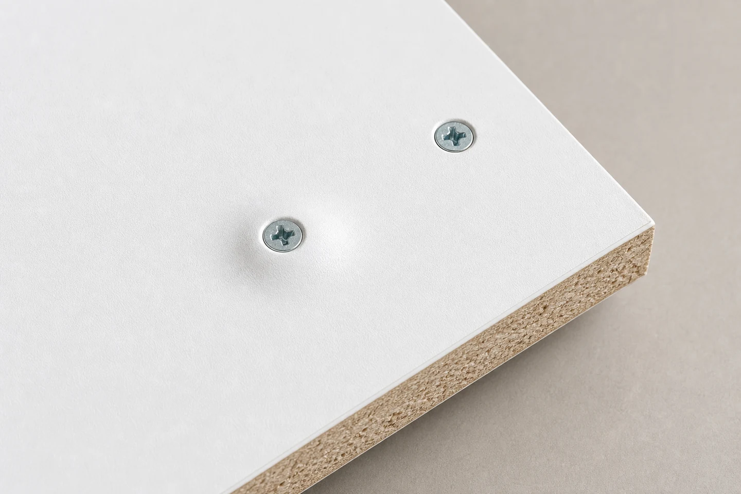
When a chipboard screw causes surface bulge, stop tightening and preserve the raised area before sanding, pressing, or removing the screw. The mound may contain displaced core particles, lifted face material, compressed debris, a hidden joint gap, unsuitable pilot conditions, head wedging, excessive clamp-up, or an edge-distance effect.
ProAirNails recommends marking screw direction, panel face, edge distance, pilot details, joint stack, tightening sequence, support, and the point when the surface first moved.
Profile the bulge before disassembly
Measure the raised area using one consistent shop method. Record peak height, width, shape, distance from the screw center, face-layer cracking, color change, head depth, and whether the mound follows the panel surface or a joint line. Photograph it under side light with a scale.
Inspect the reverse face and all accessible edges. A smooth circular rise, an elongated ridge, and a local face-layer blister can indicate different displacement paths.
Read the shape as a layer event
| Surface shape | Possible direction | Next comparison |
|---|---|---|
| Circular mound around head | Core displacement or head wedging | Section through screw axis |
| Ridge toward panel edge | Edge breakout path or limited confinement | Edge-distance map |
| Face layer lifts beyond mound | Laminate or surface bond disturbance | Layer inspection and control sample |
| Bulge appears as joint closes | Gap, debris, or clamp-up sequence | Dry-fit stack and support check |
Do not assume that driving the head deeper will flatten the panel. Additional tightening can enlarge the displaced zone, strip the core, crack the face, or pull the joint out of alignment.
Reconstruct the pilot and screw path
Record whether a pilot or clearance hole was used, along with its approved diameter, depth, position, and drilling condition. Inspect chips and dust for compacted material. After documenting the surface, remove or section a representative sample only under the approved investigation method.
Check the screw's length, diameter, thread, point, head geometry, coating, straightness, and compatibility with the panel and joint. Retain an unused screw and a correctly installed control from the same work.
Check fit-up and tightening sequence
Dry-fit representative components without the failed screw. Map gaps, warped panels, overlays, inserts, edge bands, hardware, debris, and support. A screw used to pull a large gap closed can move core material differently from one installed into a stable, fully supported joint.
Run a limited test on representative offcuts. Keep screw reference, driver, operator, panel batch, edge distance, support, and joint stack fixed. Change only one approved variable, such as the documented pilot condition or tightening sequence, and retain sections of accepted and rejected results.
Translate evidence into a ProAirNails inquiry
ProAirNails can review the screw specification, panel type and thickness, surface finish, pilot details, driver setup, edge distance, joint stack, bulge profile, and section photographs when discussing product compatibility. The final acceptance criteria belong to the furniture, cabinetry, or panel-system design.
Record installation order across the panel because an early gap, later clamp-up, or changing support point can explain why only selected positions rise.
Define whether the affected component may be repaired, requires replacement, or triggers inspection of adjacent screw positions. A cosmetic touch-up can hide a displaced layer without restoring the intended panel condition.
The limitation is important: a flat surface after rework does not establish core integrity, face-bond quality, screw holding capacity, screw-lot conformity, or long-term joint performance. Use the applicable design tests and quality criteria.
Explore the ProAirNails Chipboard Screws category and related screw range. Send panel and screw references, pilot dimensions, edge map, joint photographs, and section evidence through the ProAirNails inquiry page when a chipboard screw causes surface bulge.
FAQ
Can I sand a chipboard surface bulge flat?
Sanding may remove the visible mound but also damage the finish and hide displaced layers. Document the cause and follow the approved repair rule first.
Does a bulge mean the screw is too long?
Length may contribute, but pilot condition, head geometry, edge distance, hidden gaps, debris, panel structure, support, and tightening sequence also matter.
Will loosening the screw restore the panel?
It may reduce clamp force, but lifted face material or displaced core may remain damaged. Inspect the actual layer condition and required joint performance.
A measured ProAirNails layer review turns chipboard screw causes surface bulge into a traceable displacement problem instead of a cosmetic mound.