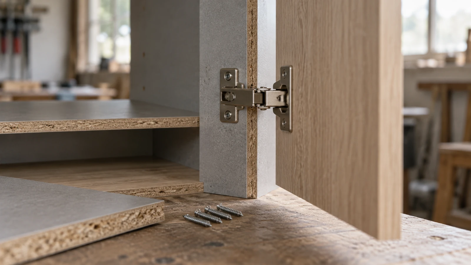

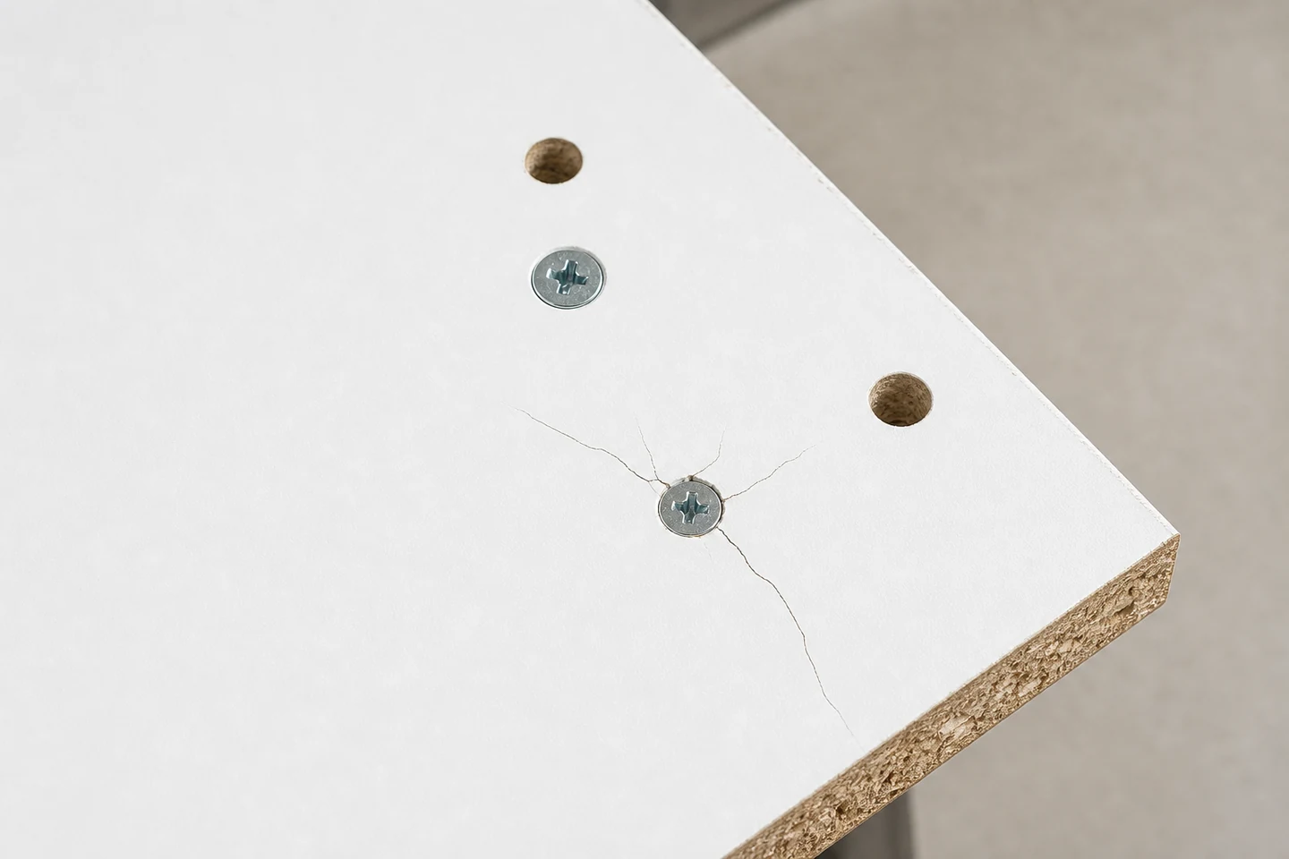
When a chipboard screw cracks laminate surface, mark the crack tips before removing the screw or hardware. Fine lines may begin during drilling, first thread engagement, head seating, hardware clamping, panel movement, or later service. The timing determines whether the next comparison should focus on hole preparation, drive control, joint fit, support, or the laminate itself.
Photograph the area in normal light and under low side light. Record screw position, panel edge, grain or texture direction, hardware outline, and the moment the crack was first visible.
Trace every branch from the screw center
Number the crack branches and measure their direction and approximate length using an approved non-damaging method. Mark whether they stop at the head, pass under hardware, connect with a drilled hole, or run toward the panel edge. Do not flex the panel to make faint cracks easier to see.
A circular chip around the head suggests a different contact history from long radial lines. Branching on one side may follow uneven seating, local support, or hardware rotation.
Build a timing record from the assembly steps
| First visible stage | Possible direction | Evidence to preserve |
|---|---|---|
| After drilling | Exit damage, dull tool, unsupported face | Hole edge and drilling setup |
| During first engagement | Hole size, edge distance, panel stress | Thread entry and panel support |
| At final head seating | Torque, head geometry, countersink fit | Driver setting and contact ring |
| After hardware loading | Joint movement or uneven bearing | Hardware flatness and service sequence |
Inspect the hole before interpreting the head
If disassembly is authorized, photograph the screw position first and remove it without levering against the laminate. Record pilot diameter, depth, breakout, countersink, debris, and distance to panel edges or nearby holes. Inspect the particleboard core for crushing, splitting, voids, or a raised plug.
Keep the screw as a matched sample. Check head underside, thread condition, point, straightness, coating, recess, and any panel material caught in the threads.
Compare the screw head with the hardware seat
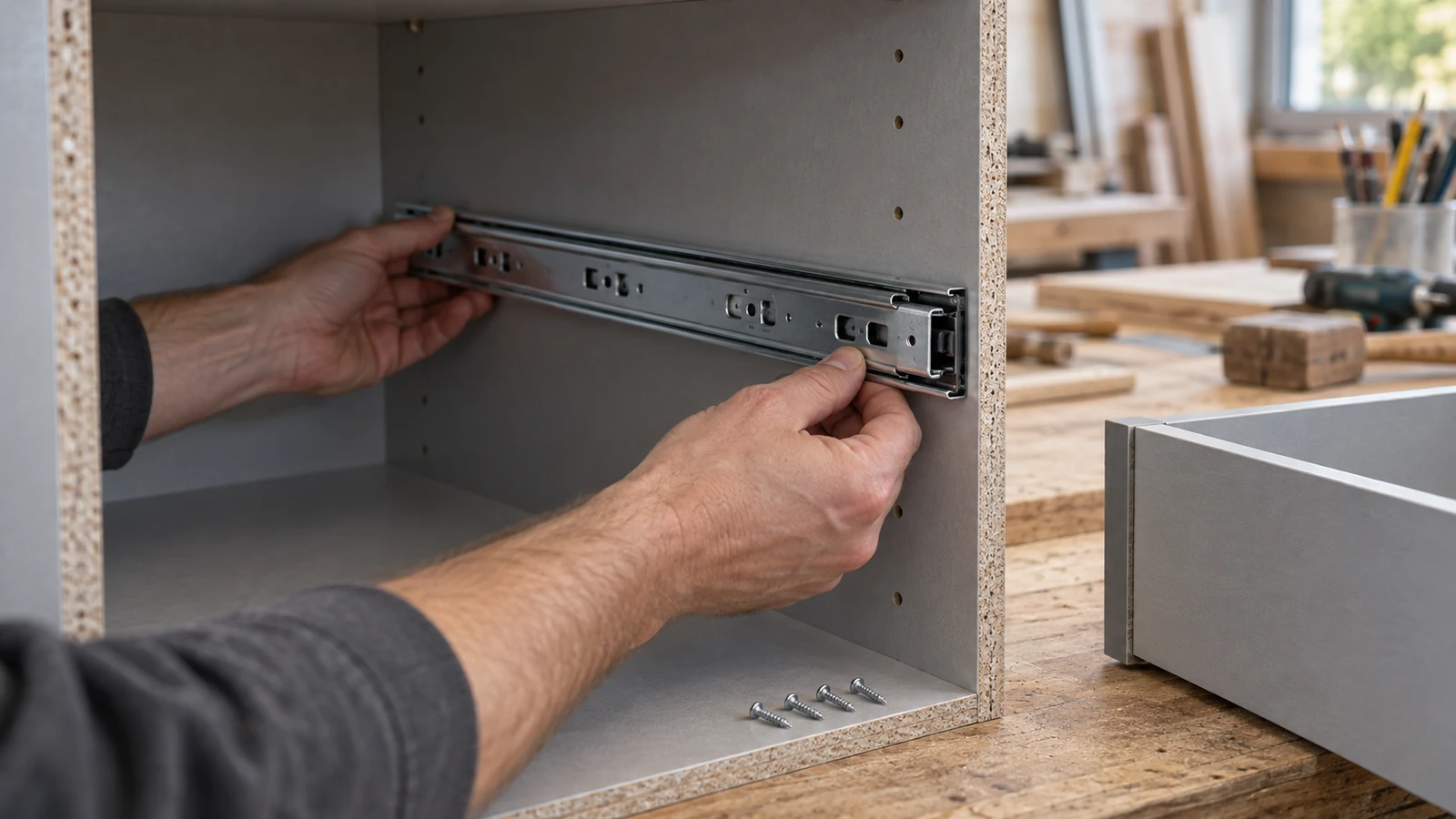
Confirm whether the head is designed to bear directly on the panel, inside a countersink, through a bracket, or against a washer or fitting. Look for a countersink angle mismatch, a sharp hardware edge, a tilted bracket, or a small bearing area concentrating load on the laminate.
A lower driver setting may reduce surface damage, but it is not a complete solution if the screw remains loose or the hardware does not seat. The joint must meet both appearance and functional criteria.
Use witness panels to isolate the variable
Prepare representative laminated particleboard samples with identified face condition and support. Keep screw, hole location, hardware, driver, and operator fixed while changing one approved variable such as pilot preparation or seating control. Mark crack onset after each assembly step.
Include an undriven hole control and a hardware-only fit check. These controls can show whether damage begins before the screw applies final clamp load. Repeat across more than one panel location because laminate and core condition can vary.
Set rework and containment boundaries
Define acceptable surface appearance, crack length, edge damage, hardware seating, screw retention, and action for rejected parts. Cosmetic filling can hide a line without resolving crushed core, poor fit, or continuing movement. Hold affected panels, screws, or hardware if a repeatable pattern follows one input.
The limitation is clear: surface inspection does not establish joint capacity, panel conformity, furniture durability, or suitability for every laminate and service condition. Those conclusions require the relevant design, material, and performance criteria.
Review the Chipboard Screw category and the broader screw range. Send screw and hardware references, panel construction, hole preparation, edge distance, crack photographs, and drive settings through the inquiry page when a chipboard screw cracks laminate surface.
FAQ
Can a cracked laminate surface be only cosmetic?
It may be limited to the finish, but the visible line alone cannot confirm that. Inspect the core, hole, hardware fit, and required acceptance criteria.
Does a larger pilot hole prevent laminate cracks?
Pilot size affects thread engagement and panel stress, but an oversized hole can reduce retention. Use the specified preparation for the screw and joint.
Should I countersink laminated particleboard?
Only when the joint design and panel process require it. Countersink geometry, depth, tool condition, support, and head fit must be controlled to avoid new damage.
Marked crack tips and step-by-step witness panels make chipboard screw cracks laminate surface a traceable assembly event rather than a hidden cosmetic defect.