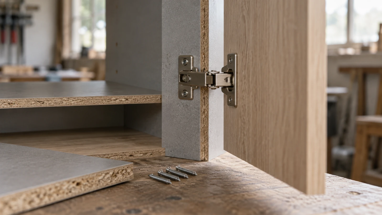

A chipboard screw edge distance test should compare the actual panel edge, pilot-hole route, screw geometry, and joint load instead of assuming that one distance works for every board and assembly. Near an edge, the screw can split the panel, break the laminate, reduce thread engagement, or appear seated while the joint has already lost useful material.
ProAirNails recommends testing a ladder of distances with the production screw and tool, then recording visible damage and mechanical outcome separately.
Define the edge reference
State whether distance is measured from the screw centerline to the nearest panel edge, from the hole wall, or from a corner. Record panel thickness, edge type, face layer, grain or particle direction where relevant, and whether the edge is exposed, banded, cut, or drilled.
Build a distance ladder
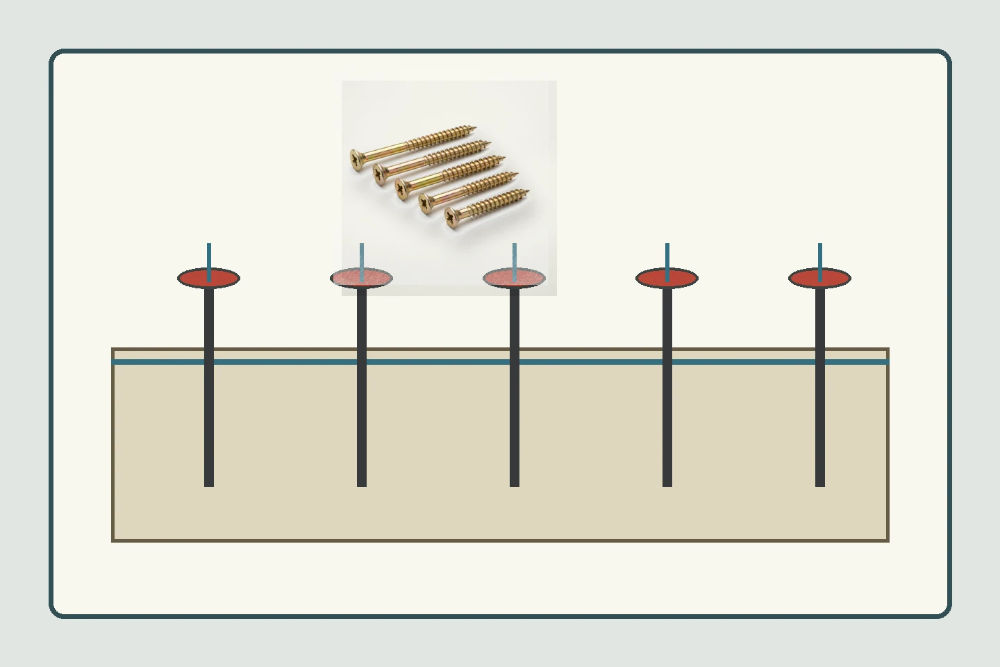
Use several planned distances that cover the production design, a closer risk case, and a larger comparison. Keep screw diameter, length, pilot, speed, tool, and joint hardware constant while changing only the edge distance. A single successful location cannot show the transition to breakout.
| Test field | Keep or vary | Record |
|---|---|---|
| Edge distance | Vary by defined ladder | Centerline and nearest edge |
| Panel | Keep baseline, then stratify lots | Thickness, face, lot, moisture |
| Screw | Keep for comparison | Diameter, length, thread, point, head |
| Pilot | Keep route and tool | Diameter, depth, alignment, age |
| Outcome | Observe separately | Split, breakout, seating, pull-out, torque |
Inspect the edge before loading
Record chips, crushed laminate, pre-existing cracks, edge banding, and cut quality. Mark each hole so the test location remains traceable. A damaged edge can make a good screw look weak; an unusually dense area can make a marginal distance look acceptable.
Control the installation sequence
Use the production bit, tool, access, speed, pressure, and pilot procedure. Record head seating, gap closure, surface bulge, cam-out, and board movement. Keep failed screws and panel pieces. If the joint has several screws, define the order because a nearby screw can change the stress around the next hole.
- Mark centerlines and edge references.
- Measure pilot holes before driving.
- Use fresh identified screws and bits.
- Photograph the edge before and after.
- Separate first-screw and sequence effects.
Measure more than visible splitting
The chipboard screw edge distance test should record surface breakout, hidden edge cracks where accessible, seating torque, pull-out or joint movement when relevant, and reassembly condition. A clean face does not prove the internal particle structure remained engaged.
Use a decision matrix
| Finding | What it may indicate | Next step |
|---|---|---|
| Visible edge split | Distance, pilot, point, or edge condition | Hold distance and compare controlled inputs |
| Laminate breakout | Head, speed, support, or edge layer | Review entry and surface support |
| Good face, low pull-out | Insufficient internal engagement | Inspect thread path and panel lot |
| High torque, no gap closure | Bottoming or misalignment | Review length, pilot, and hardware |
| Only one lot fails | Panel variation | Stratify results by board lot and location |
Connect to furniture design limits
Designers should state minimum edge distance, corner rules, screw spacing, panel orientation, hardware clearances, and repair authority in the assembly documentation. The test supports that design boundary; it does not create a universal value for all chipboard, screw types, or furniture loads.
Use standards as references only
The official ISO 2859-1:2026 page can support attribute sampling for a defined screw lot. The ISO 16047 page addresses torque/clamp-force testing for threaded fasteners under its scope; a chipboard furniture joint requires its own specimen, substrate, friction, and failure definition. Neither page supplies a universal chipboard edge-distance rule.
Prepare an evidence-based RFQ
Send panel drawings, edge type, thickness, screw specification, pilot route, tool, hardware, distance ladder, photographs, expected loads, sample quantity, acceptance, packaging, and change controls. ProAirNails can discuss chipboard screws, screw products, the product range, and samples through the inquiry page.
Keep the result inside its boundary
An edge-distance coupon cannot represent every panel lot, climate, consumer tool, joint load, impact, or repeated assembly. Visible appearance is not complete structural evidence. ProAirNails can provide agreed product and sample information, while qualified furniture designers and manufacturers own the final joint approval.
Repeat the chipboard screw edge distance test after any change to panel supplier, edge banding, screw point, pilot diameter, or assembly sequence. These changes can move the failure boundary.
Keep the distance ladder with the approved furniture drawing and first-piece record. This lets production see the tested margin instead of treating the minimum edge distance as an unexplained number.
When the panel edge is banded or pre-drilled, preserve that preparation in the specimen. An unfinished cut edge and a sealed production edge may not have the same breakout behavior. Record the assembly sequence and whether a nearby screw was already loaded. These controls keep chipboard screw edge distance test results relevant to the furniture actually being built.
Use chipboard screw edge distance test to find the safe working margin between a clean joint and an edge that has already started to fail.
FAQ
What is edge distance?
It is the defined distance from the screw reference centerline or hole to the nearest panel edge or corner.
Why use several distances?
A ladder shows where splitting, breakout, or engagement changes instead of recording one isolated success.
Should pilot holes be controlled?
Yes. Diameter, depth, alignment, tool, and hole condition can materially change edge behavior.
Can a clean face hide failure?
Yes. Internal particle damage or low thread engagement may not be visible from the face.
Does torque alone prove the edge is safe?
No. Record seating, splitting, pull-out or movement, panel condition, and the actual joint outcome.
When should board lots be separated?
Separate them when density, thickness, face, moisture, supplier, or edge preparation differs.
Can ISO 16047 set the edge rule?
No. It addresses threaded-fastener torque/clamp-force testing under its scope, not a universal chipboard edge distance.
What should be photographed?
Photograph panel edges, marks, pilot holes, installation, breakout, splits, and retained failed pieces.
When should the design be reopened?
Reopen it after changes to panel, screw, pilot, edge preparation, hardware, tool, or joint geometry.
What belongs in an RFQ?
Include the panel, edge, screw, pilot, tool, distance ladder, load, photos, samples, and acceptance rule.