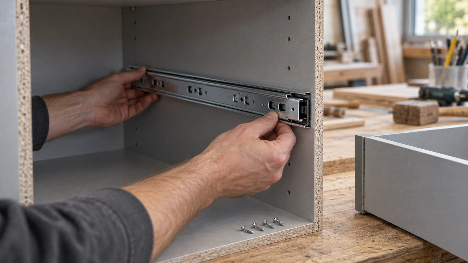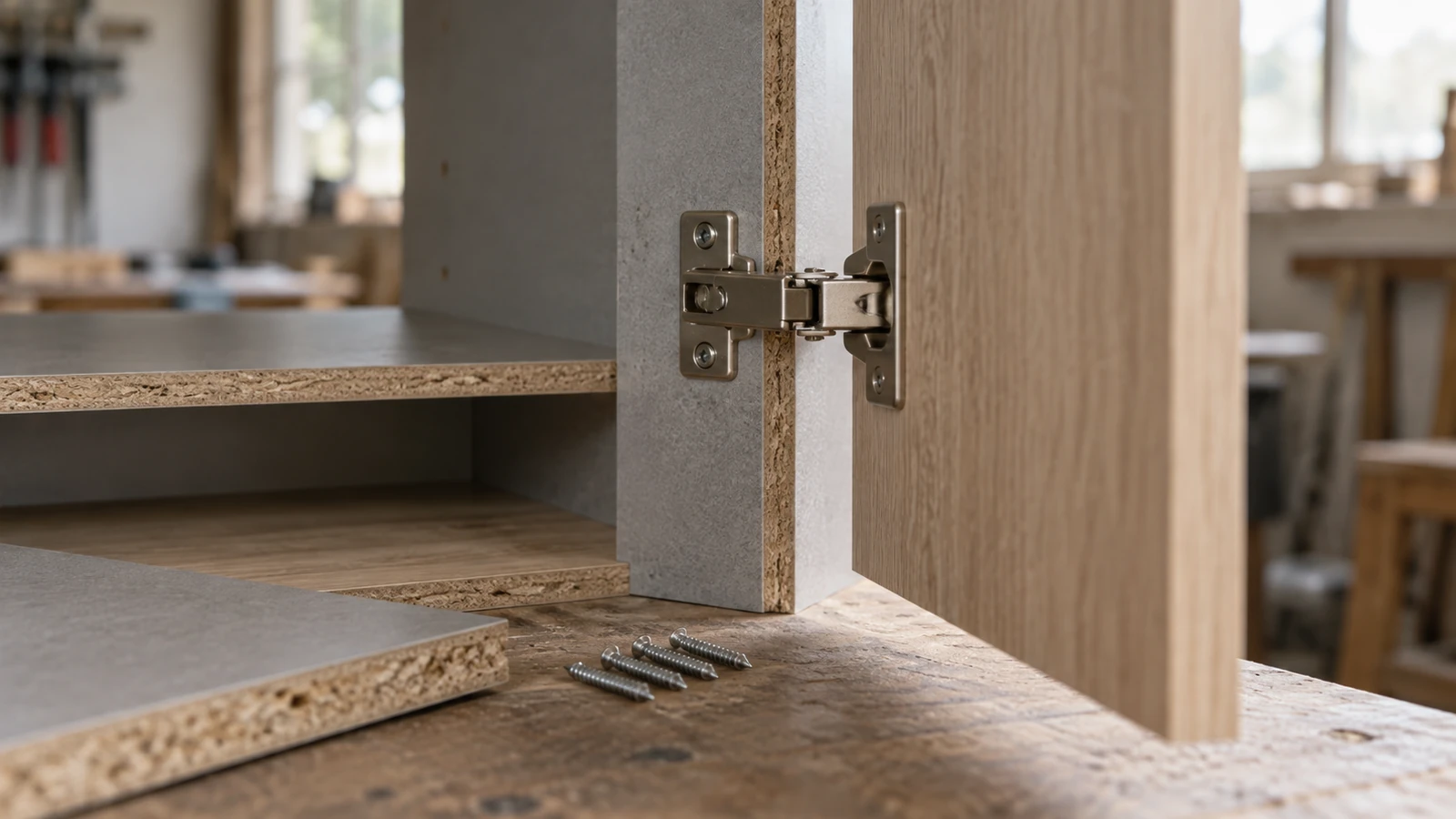

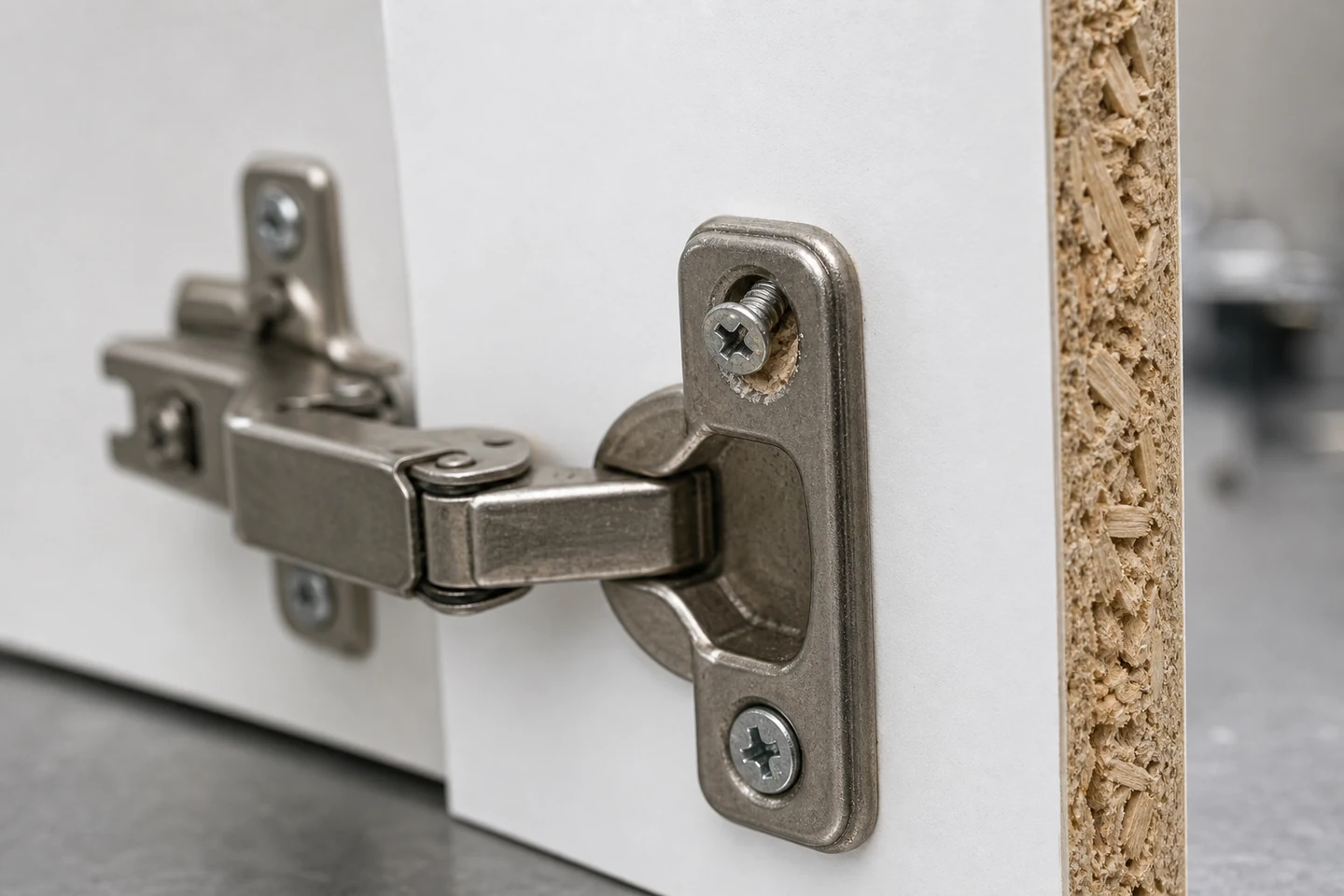
A chipboard screw loosens over time when the joint loses enough clamp or thread support for movement to continue. The cause may involve an oversized or damaged hole, excessive installation torque, insufficient engagement, hardware misalignment, repeated opening cycles, vibration, moisture change, board damage, edge proximity, or a repair that did not restore the receiving material.
Tightening the screw again can temporarily remove play while destroying evidence about the hole and joint. Record the condition before adjustment.
Establish a joint baseline
Identify the board reference and thickness, screw diameter and length, head and thread form, pilot preparation, hole location, hardware, installation method, and original tightening criterion. Photograph the hardware closed and open, including the board edge and any visible gap.
Mark the screw head and hardware with a removable inspection reference where permitted. Record hinge alignment, door mass, adjustment settings, and whether other screws share the load.
Log movement at fixed cycle checkpoints
Use the service action that represents the product: door opening, drawer movement, bracket loading, vibration, or another approved cycle. Inspect at defined intervals rather than only after obvious failure. Record play, head rotation, hardware shift, noise, surface crushing, and any change in alignment.
- Baseline after installation and settling.
- Early checkpoint for installation-related movement.
- Intermediate checkpoints for trend development.
- Final checkpoint or stop when the acceptance limit is reached.
Separate rotation from hole enlargement
| Observed clue | Possible mechanism | Inspection direction |
|---|---|---|
| Head reference rotates | Loss of clamp, vibration, hardware movement | Track rotation and joint gap together |
| Head stays fixed but hardware moves | Clearance, plate deformation, surface crushing | Inspect the complete hardware interface |
| Screw can be pulled or rocked | Hole growth, stripped particles, insufficient engagement | Preserve and open the hole under procedure |
| Looseness changes with humidity | Board or connected-material movement | Record environment and material condition |
Do not identify the mechanism from rotation alone. Hardware slots and adjustment features can move while the screw remains engaged, and a damaged hole can lose stiffness without visible head rotation.
Open one failed hole and one control
After recording the assembled condition, remove the screw using the approved method. Keep its location and orientation identified. Inspect for compacted particles, polished thread tracks, an oversized pilot, edge breakout, moisture swelling, split laminate, or a hole that intersects another fixing.
Compare a nearby stable fixing from the same assembly when the investigation permits. Measure engagement and hole preparation rather than assuming both positions are identical because they use the same hardware.
Review installation torque as a process window
Too little tightening may leave the hardware unclamped. Too much can strip the particle structure, crush the surface, deform the hardware, or create a joint that feels tight only at installation. Define a controlled stop method suitable for the screw, board, pilot, and hardware instead of relying only on operator feel.
Repeat a small installation-and-cycle matrix on representative board. Keep screw, pilot, hardware, edge distance, and environment fixed while comparing approved tightening settings.
Choose repair by remaining material condition
A larger screw, insert, relocated fixing, replacement panel, or purpose-designed repair system changes the load path and may affect hardware fit, edge distance, appearance, and future service. Select the repair under the product design and quality requirements after the hole condition is known.
Do not repeatedly retighten a screw that spins or immediately loses clamp. Repeated driving can remove more material and reduce the options for a controlled repair.
Define the service acceptance rule
State the permitted movement, inspection interval, cycle count, environmental conditioning, and trigger for rework or containment. Keep the log with board lot, hardware, screw, pilot, tightening method, and repair history so later failures can be compared.
The limitation is scope: a bench cycle log does not establish full furniture life, safety, structural capacity, or suitability for every board lot and use condition. Those conclusions need the applicable design and validation program.
Review the Chipboard Screw category and the broader screw range. Send board and screw references, pilot preparation, hardware, tightening method, cycle log, environment, and hole photographs through the inquiry page when a chipboard screw loosens over time.
FAQ
Why does a cabinet hinge screw keep coming loose?
Possible causes include a damaged or oversized hole, stripped particleboard, poor engagement, hardware movement, misalignment, repeated cycling, excessive installation torque, or changing moisture conditions.
Can thread-locking adhesive fix a loose chipboard screw?
An adhesive may not restore missing board material or correct hardware alignment, hole damage, and load path. Use only a repair method approved for the board, screw, hardware, and product requirements.
Should the loose screw be replaced with a larger one?
Not automatically. A larger screw changes hole expansion, edge margin, hardware clearance, and thread engagement. Inspect the remaining material and verify the repair on representative samples.
A checkpoint log shows when and how a chipboard screw loosens over time, making the repair decision evidence-based.