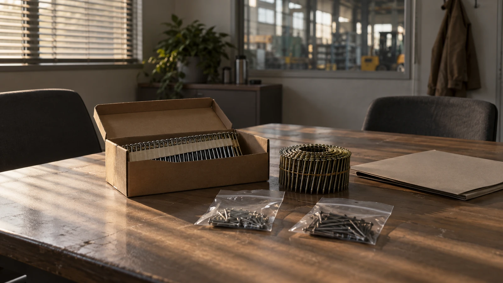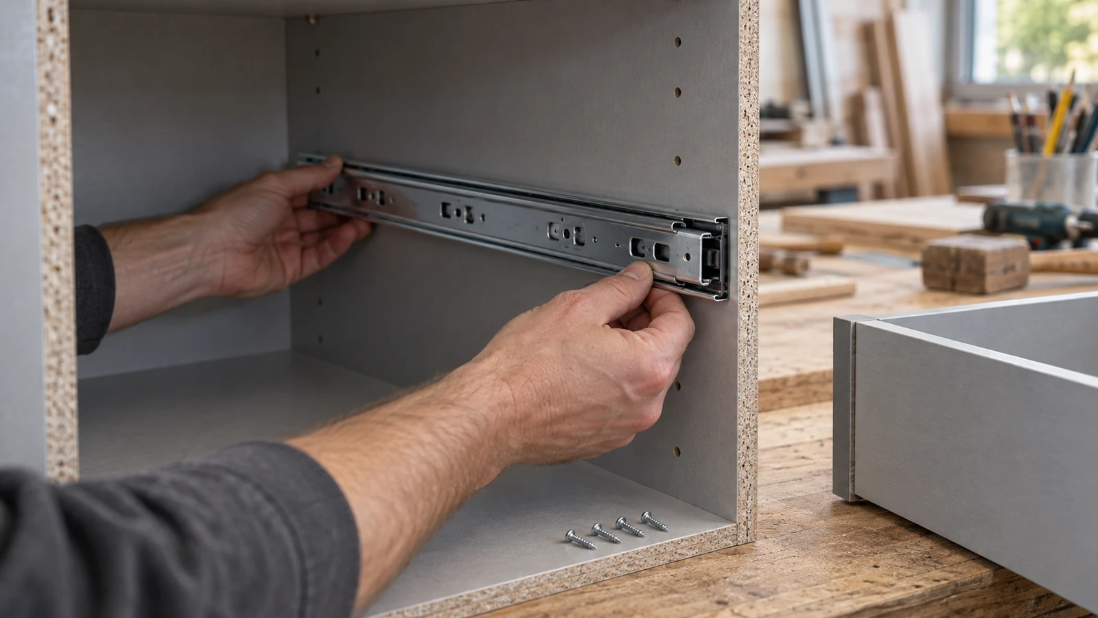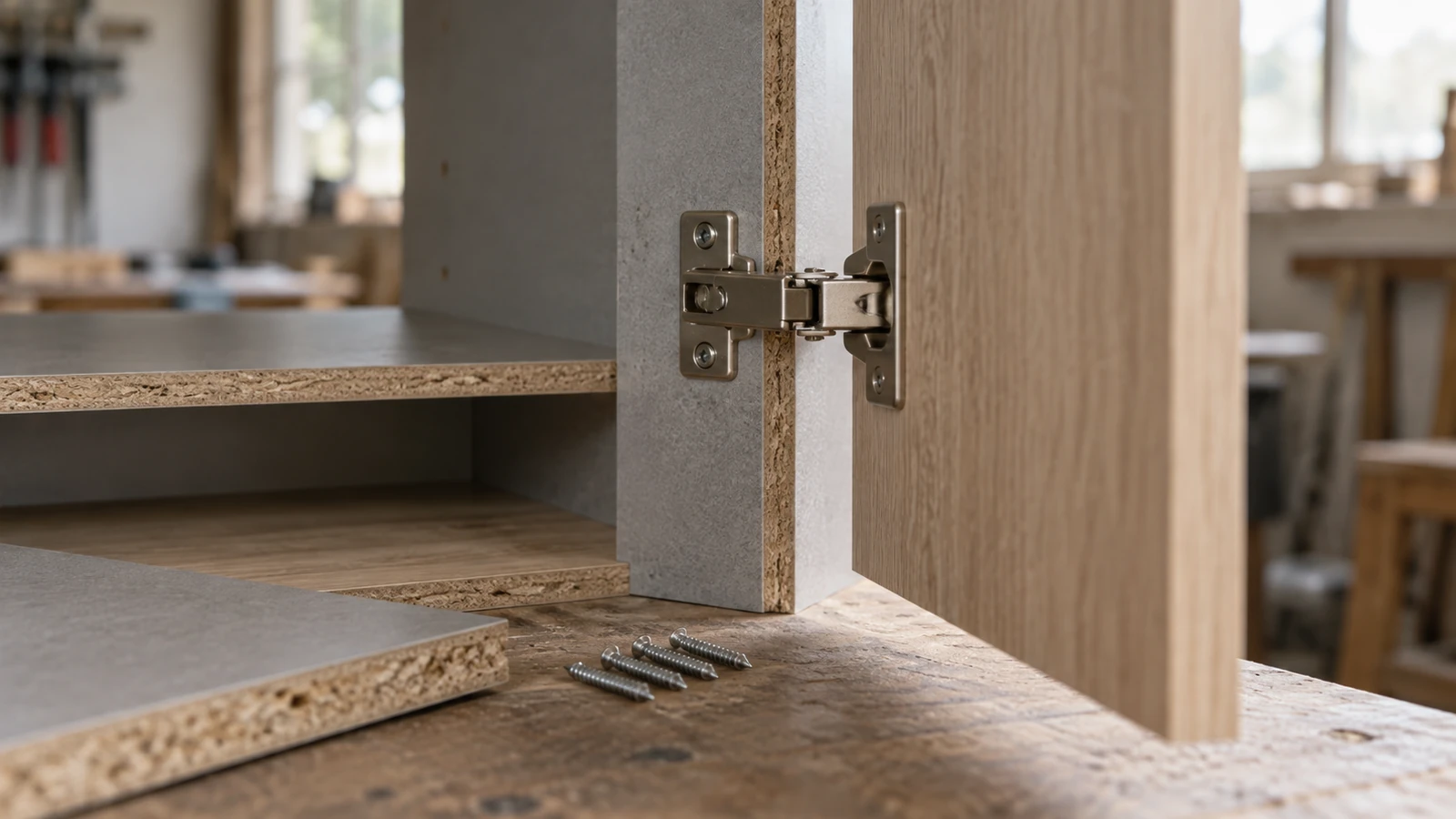

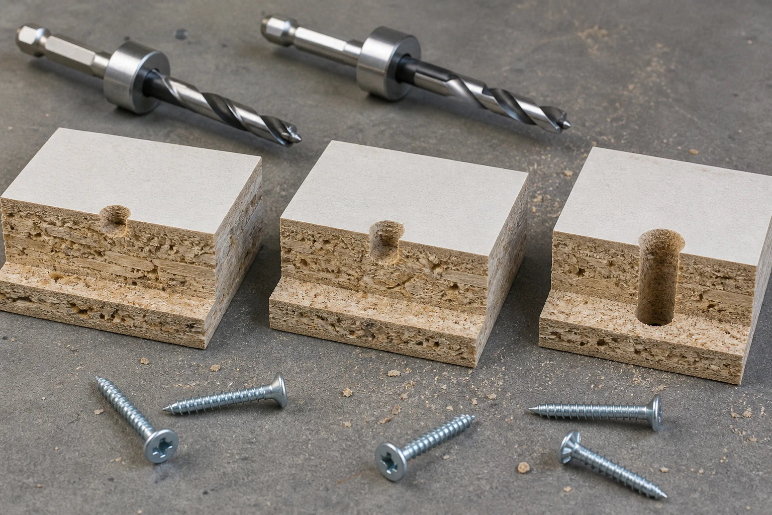
A chipboard screw pilot hole depth test should compare a declared ladder of hole depths while keeping diameter, board, screw, edge distance, tool, and seating endpoint fixed. The useful answer is a working depth window for a named joint—not a single depth copied from an unrelated material.
ProAirNails recommends testing shallow, target, and deep conditions beside an approved baseline, then recording drive behavior, joint closure, splitting, bulge, stripping, and the hole condition after removal. Depth is only one part of the joint geometry.
Reference depth from a real surface
State whether depth begins at the board face, hardware surface, countersink, edge, or a stepped shoulder. Record instrument and resolution. A drill-stop position is not automatically the actual hole depth when chips remain, the bit point extends beyond the cutting diameter, or the board surface compresses.
Separate depth from diameter
Use the same verified bit diameter and geometry across the depth ladder. Record pilot diameter, bit type, point, runout where relevant, chip clearing, and drilling direction. If depth and diameter change together, the test cannot identify which variable changed the outcome.
| Controlled field | Record | Why it matters |
|---|---|---|
| Board | Type, batch, thickness, density, condition | Controls thread support |
| Hole diameter | Bit, measured size, geometry | Changes material engagement |
| Hole depth | Actual depth and reference surface | Defines prepared thread path |
| Screw | Diameter, length, thread, head, lot | Defines engagement and seating |
| Drive endpoint | Torque, depth, gap, or head condition | Makes comparisons consistent |
Prepare a depth ladder
Select levels around the current or proposed process, including a no-pilot or established control only when safe and relevant. Distribute levels across representative board positions rather than placing every deep hole in one panel edge. Randomize drive order so bit wear or operator learning does not follow the depth sequence.
- Number panels and holes before drilling.
- Verify the stop against actual hole depth.
- Clear chips with one declared method.
- Use fresh comparable holes for each level.
- Retain sectioned or removed-hole samples.
Keep edge distance and spacing fixed
Depth interacts with nearby free edges and previous holes. Use a drawing for hole location, edge distance, spacing, board orientation, and joint alignment. A deep pilot near an edge may produce a different failure pattern from the same depth in a broad face area.
Drive to a declared endpoint
Choose a seating rule that fits the joint: head flush condition, hardware closure, joint gap, torque window, or another approved endpoint. Record tool, bit, speed, alignment, clamp state, and any intervention. Do not keep turning after the endpoint merely to collect a larger torque value.
Read both installation and joint evidence
Observe start stability, required turns, drive signature, seating, head or recess damage, board bulge, splitting, stripping, gap, alignment, and movement. Where removal is part of the method, inspect thread debris, hole walls, bottom condition, and screw threads. A smooth drive is not automatically a strong joint.
Interpret the depth pattern
| Result pattern | Possible interpretation | Next check |
|---|---|---|
| Shallow holes split or bulge | High displacement near entry | Review diameter, depth, edge, and board |
| Middle depths seat consistently | Candidate process window | Repeat across board and lot variation |
| Deep holes strip early | Reduced effective thread support | Inspect engagement and bottom geometry |
| All levels vary widely | Depth may not be dominant | Check board, diameter, tool, and alignment |
| Drive passes, joint gap fails | Seating signal does not equal closure | Review hardware and assembly geometry |
Confirm actual depth
Use a suitable depth method, section representative specimens where appropriate, and account for the bit point. Chips packed at the bottom can make a hole appear complete while reducing usable depth. Record whether measurements occur before or after cleaning and whether the hole is damaged by the measurement.
Keep torque evidence in scope
The official ISO 16047:2005 page addresses torque/clamp-force testing for threaded fasteners under specified conditions. It does not establish a chipboard pilot-hole depth or prove joint capacity. Any torque signal in particleboard needs a declared application method and suitable correlation.
Sample board variation deliberately
The ISO 2859-1:2026 page describes lot-by-lot sampling by attributes. The buyer must still define board and screw lots, depth levels, panel positions, failure modes, sample count, acceptance, and response. Do not average away a cluster at one board edge or density zone.
Convert the window into production control
Specify bit and revision, nominal depth and allowable window, stop or jig, verification frequency, chip-clearing route, tool, board, screw, endpoint, inspection, and reaction. Challenge the setup after bit replacement, stop movement, board change, or a run of abnormal joints.
Send a depth-ready inquiry
Provide screw dimensions and thread, board specification, joint drawing, pilot diameter and depth ladder, edge distance, hardware, tool, endpoint, results, defects, and acceptance. ProAirNails can discuss chipboard screws, the wider screw range, related products, and samples through the inquiry page.
Do not turn one depth into a universal rule
A chipboard screw pilot hole depth test cannot prove every board density, moisture condition, screw geometry, joint, load, or service life. It does not replace furniture design, structural evaluation, or safe tool control. ProAirNails can support identified screw evidence; the designer owns the final joint.
Retain samples from shallow, accepted, and deep conditions with their hole and drive records. Repeat the chipboard screw pilot hole depth test after changes to board, bit, diameter, depth stop, screw, tool, hardware, edge distance, or endpoint.
Use the chipboard screw pilot hole depth test to establish a verified working range and a reaction when the drilling process leaves it.
FAQ
Is pilot-hole depth the same as drill-stop position?
No. Bit point, surface compression, chips, fixture play, and stop geometry can change actual depth.
Why keep pilot diameter fixed?
Changing diameter and depth together prevents a clear conclusion about either variable.
Should a no-pilot control be included?
Include it only when relevant, safe, and approved for the material and joint question.
What is a depth ladder?
It is a planned set of shallow, target, and deep conditions around the proposed process.
Why randomize drive order?
It prevents bit wear, board sequence, or operator learning from following the depth levels.
Can smooth driving prove joint strength?
No. Record closure, gap, damage, movement, and any required performance evidence separately.
How can actual depth be verified?
Use a suitable depth method and section representative samples where appropriate, accounting for the bit point.
What indicates an overly deep pilot?
Early stripping, reduced engagement, abnormal seating, or weakened joint evidence may indicate excess depth.
When should the setup be challenged?
Check after bit, stop, board, screw, tool, hardware, or abnormal-result changes.
What belongs in production control?
Specify bit, diameter, depth window, reference, verification, chip clearing, endpoint, sampling, and reaction.