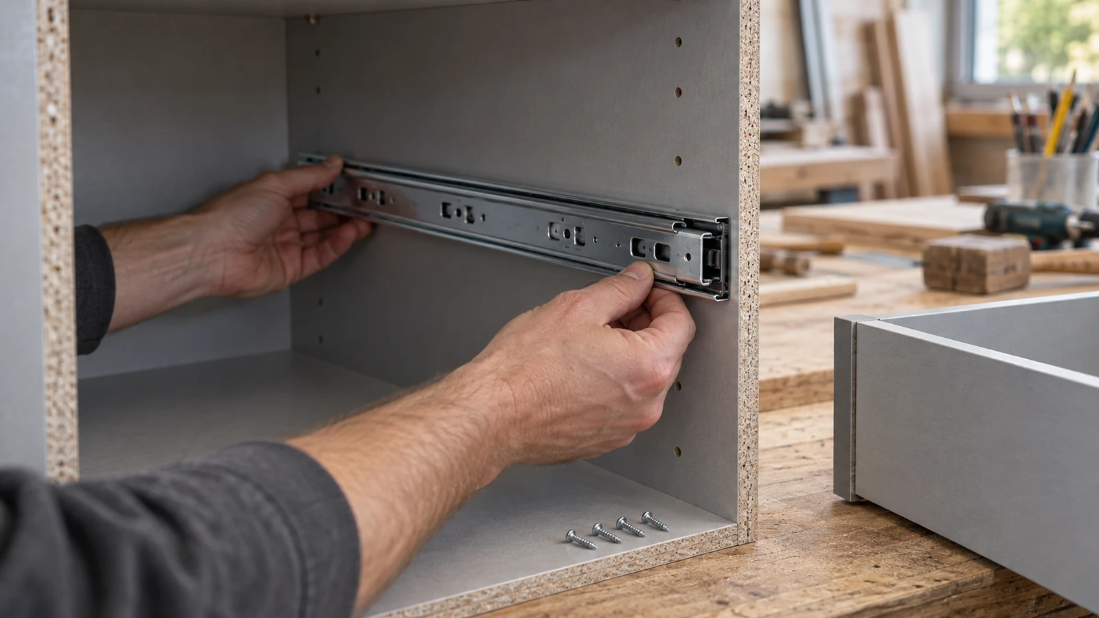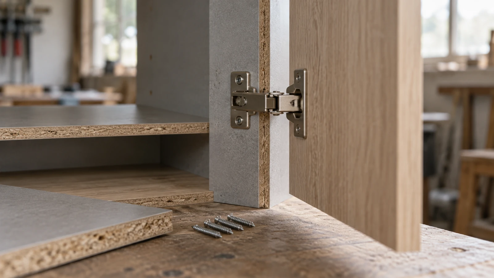

A chipboard screw may need a pilot hole when the board splits, bulges, crumbles, drives inconsistently, or must be installed close to an edge. It may not need one in every material and joint. The reliable answer comes from a controlled comparison using the actual board, screw, tool, and edge position.
This chipboard screw pilot hole test avoids a universal drill-size claim. Board density, face layers, core structure, screw diameter, root geometry, point, length, head form, moisture, and driving setup all influence the result.
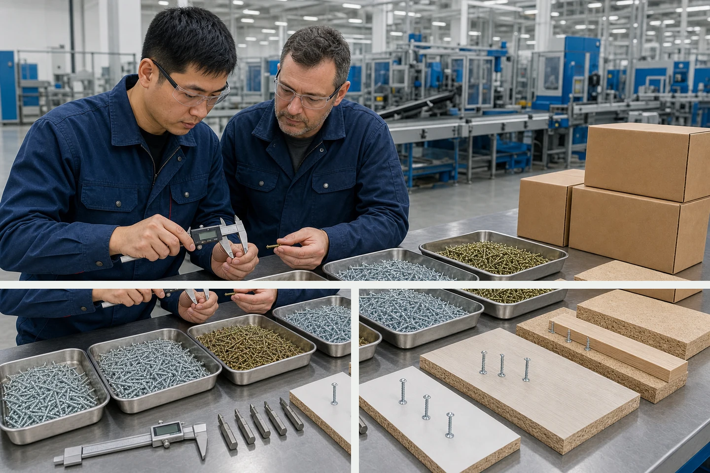
Prepare three matched specimens
- Cut three pieces from the same board area and mark the same screw location on each. Keep thickness, edge distance, grain or surface direction, and support identical.
- Leave specimen A without a pilot hole. Drill specimen B with the smaller candidate bit. Drill specimen C with the larger candidate bit. Keep depth and alignment controlled.
- Use screws from the same product batch and the same driver, bit, speed approach, and stopping method. Do not change clutch or operator technique between specimens.
- Drive the screw once. Repeated removal and reinsertion changes the hole and should be treated as a separate test.
- Photograph the face and edge, record driving behavior, then cut or break open a spare sample if the internal board response needs inspection.
Compare the result, not just the driving effort
| Specimen | Possible useful result | Warning signs |
|---|---|---|
| No pilot hole | Simple installation with acceptable seating and intact board | Edge splitting, surface bulge, crumbling, high variability, head damage |
| Smaller pilot hole | Reduced splitting while threads still form a clear path in the board | Little improvement, drill wandering, damaged surface, inconsistent depth |
| Larger pilot hole | Lower insertion resistance where the application permits it | Poor thread engagement, spinning, easy pullout, unstable head seating |
The table is a diagnostic guide, not an acceptance specification. A low driving effort is not automatically better if the thread no longer engages enough material for the intended use.
Hold these variables constant
Board: use the same product, thickness, conditioning, and cut direction. A dense face and a coarse core can respond differently.
Fastener: keep diameter, length, thread, point, head, recess, and coating constant. A different screw creates a different experiment.
Location: test both a typical field position and the most demanding permitted edge or end position. Do not use an unsafe or unapproved edge distance merely to force a failure.
Driver: keep the bit fit, alignment, speed approach, and stop method consistent. A damaged recess or angled drive can look like a pilot-hole problem.
Create a result sheet that another person can repeat
Record the board manufacturer and reference where available, board thickness, conditioning notes, screw description, candidate drill bits, pilot depth, edge distance, driver and bit, and operator. For each specimen, note splitting, bulging, crumbling, seating, recess condition, spinning, and any measured torque only when suitable calibrated equipment and a defined method are available.
Attach face, edge, and opened-section photographs. The purpose is not to produce a scientific-looking form; it is to make the decision traceable when the board batch, screw, or production location changes.
Decide what the test can and cannot prove
The main limitation is scope: the comparison can show which preparation gives the most consistent installation in the tested specimens. It does not by itself establish long-term pullout resistance, structural capacity, furniture safety, repeated assembly performance, or compliance with a product standard. Those outcomes need the appropriate design and verification method.
A pilot hole may also add time, drill wear, dust, alignment risk, and another process-control point. The benefit should solve a defined failure rather than become an automatic step copied to every screw and board.
Use the winning sample as the new reference
Keep the selected specimen, screw box, drill reference, result sheet, and photographs together. Define when the check must be repeated, such as after a board change, screw change, tool change, or new edge position.
A controlled chipboard screw pilot hole reference is useful only while the tested materials and method remain traceable.
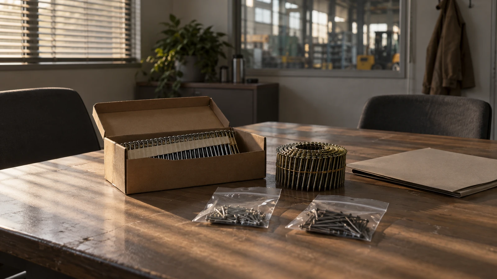
Review the Chipboard Screw range and related screw products. The factory page gives manufacturing context, and the inquiry form can carry the current screw, board reference, failure photographs, and test result.
FAQ
Is one pilot hole size suitable for every chipboard screw?
No. Screw geometry, board construction, edge position, installation method, and performance requirement vary. Compare controlled candidates in the actual material.
Why can a pilot hole that is too large be a problem?
It can remove material needed for thread engagement, allowing the screw to spin or reducing the stability of the installation. The result must be judged as a complete joint.
Should the pilot hole be tested near the board edge?
Test the demanding position that is permitted by the product or project requirements. Edge behavior can differ from a center test, but an unapproved edge distance should not be used.
A documented chipboard screw pilot hole comparison provides a defensible starting point without pretending that one drill size fits every board.