
A chipboard screw reassembly cycle test should define one complete cycle as installation, joint evaluation, controlled removal, hole inspection, and reinstallation—not simply drive the same screw repeatedly until the board fails. The useful result is how a named joint changes from one assembly state to the next.
ProAirNails recommends comparing repeated holes with fresh-hole controls while recording screw identity, chipboard condition, pilot preparation, tool settings, seating behavior, removal, joint gap, and damage. This supports a specific furniture or panel decision without implying unlimited screw reuse.
Define the lifecycle question
Decide whether the product is expected to be assembled once, serviced once, moved several times, or used in a repeated-access panel. State the required number of cycles and the function that must remain acceptable: joint closure, alignment, pull resistance, appearance, movement, or controlled removal.
Name the joint not just the screw
Record board type, density where known, thickness, face or edge location, grain or layer orientation, moisture condition, edge distance, hole spacing, pilot diameter and depth, clearance hole, countersink, bracket, washer, and clamped geometry. The same screw can behave differently in an edge hole and a face hole.
| Variable | Fix or record | Reason |
|---|---|---|
| Board | Type, thickness, batch, condition | Controls thread support and damage |
| Hole | Location, pilot, depth, alignment | Defines the material engaged |
| Screw | Diameter, length, thread, head, finish, lot | Preserves product identity |
| Drive | Tool, bit, speed, torque or depth rule | Controls seating energy |
| Cycle | Install, inspect, remove, inspect, reinstall | Makes results comparable |
Prepare fresh-hole controls
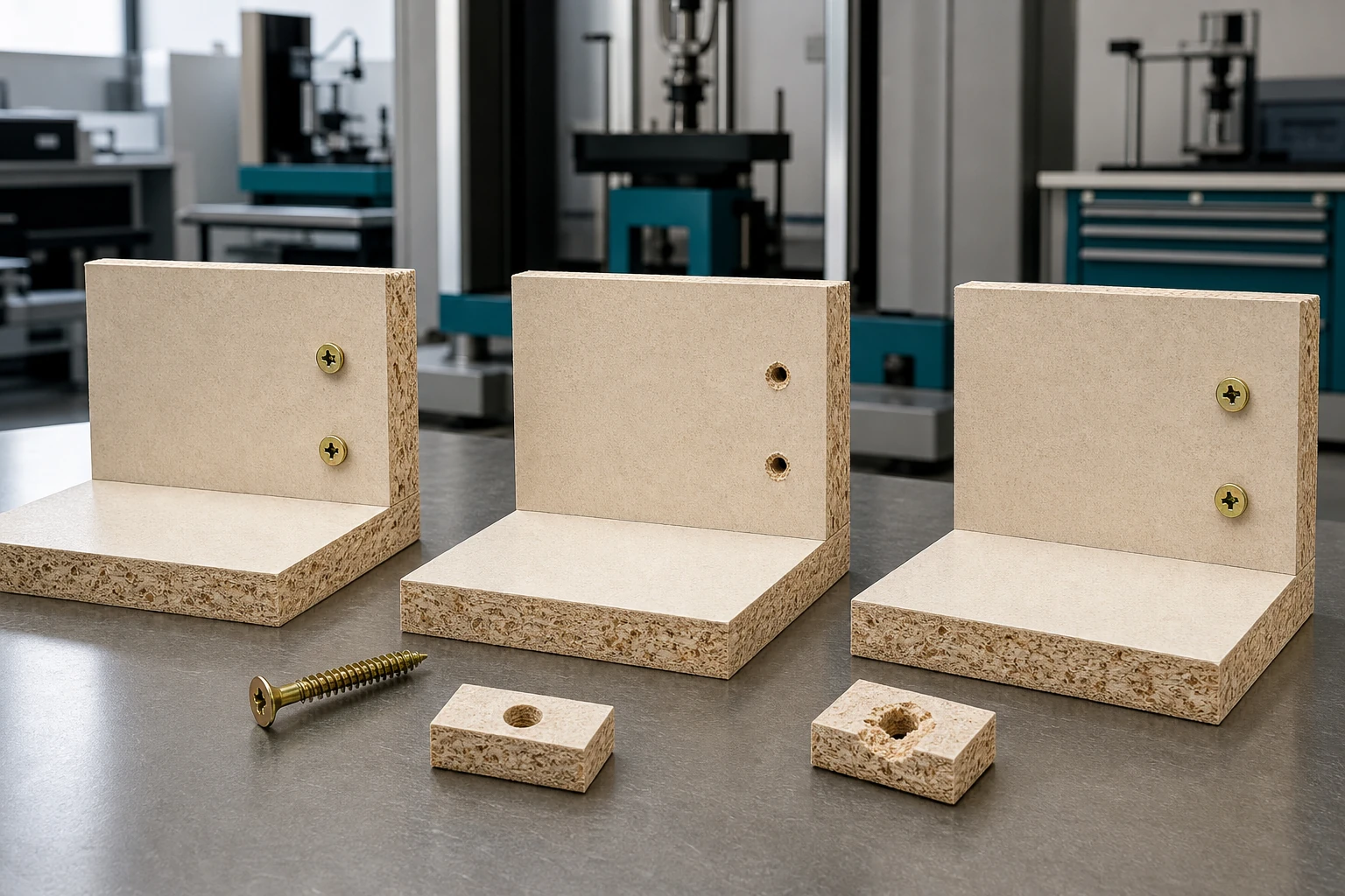
For each later cycle, install matched screws into unused holes in comparable board. This separates changes caused by the reused hole from variation in board or operator. Where screw reuse is also under study, add groups for a new screw in a reused hole and a reused screw in a fresh hole. Label every combination clearly.
Control the first assembly
Use the approved pilot and clearance route. Align the joint before driving and apply the declared clamp condition. Record seating torque or tool setting, final head position, joint gap, visible cracking, bulge, stripping, and any intervention. An overdriven first cycle can pre-damage the hole and make later results misleading.
- Number every specimen and hole.
- Use the same measurement references each cycle.
- Retain stripped or damaged screws.
- Photograph the hole before removing debris.
- Keep fresh and repeated controls physically separated.
Remove without inventing extra damage
Use a matching, unworn bit aligned with the recess. Declare removal speed and support the joint consistently. Record peak or characteristic removal torque where measured, bit cam-out, recess damage, screw bending, coating change, debris, and whether the screw can be removed normally. Prying the joint apart adds a force outside the intended cycle.
Inspect the hole between cycles
Observe loosened particles, wall polishing, enlarged entry, stripped threads, cracking, breakout, misalignment, and debris. Do not automatically refill, rotate, or clean the hole unless that action belongs to the service procedure. If debris is removed, define the method and keep the removed material as evidence where useful.
Reassemble to a declared endpoint
Choose whether the operator returns to a torque, depth, head-flush condition, or joint-gap target. Each endpoint answers a different question. Driving to the original tool setting may no longer create the original clamp condition in a damaged hole. Record rotations, seating signature, final position, and whether the screw continues to turn without closing the joint.
Read the pattern across cycles
| Pattern | What it may mean | Next evidence |
|---|---|---|
| Lower seating resistance, stable gap | Hole support changing before visible looseness | Continue declared cycle and compare fresh control |
| Gap increases after reassembly | Reduced clamp or alignment loss | Joint movement and section inspection |
| New screw improves reused hole | Screw wear contributes | Inspect thread and recess condition |
| Reused screw passes in fresh hole | Board hole dominates | Compare hole damage and material density |
| Edge breakout appears | Geometry or accumulated damage | Review pilot, edge distance, and cycle target |
Keep torque evidence in context
The official ISO 16047:2005 page addresses torque/clamp force testing for threaded fasteners under specified conditions. A chipboard joint is a different application system, and drive torque alone is not proof of retained clamp force or pull-out performance. Define any instrumentation, rate, and endpoint in the buyer's method.
Sample material variation deliberately
The ISO 2859-1:2026 page can support attribute sampling for a declared lot, but it does not choose board locations, cycle count, failure definition, or acceptance. Distribute specimens across representative panels and positions. Report clustered failures instead of averaging them away.
Convert the lifecycle into an inquiry
Send screw dimensions, thread and head, bit, finish, board specification, joint drawing, hole preparation, edge distance, tool settings, cycle definition, measurements, required service count, defects, and acceptance. ProAirNails can discuss chipboard screws, the wider screw range, related products, and samples through the inquiry page.
Stop where the evidence stops
A chipboard screw reassembly cycle test cannot prove unlimited reuse, every board density, long-term creep, vibration life, or structural safety. Passing a declared number of controlled cycles does not authorize more cycles. ProAirNails can support product evidence, while the furniture or panel designer owns the service requirement and final joint approval.
Set termination rules before testing: visible split, stripped hole, uncontrolled rotation, gap outside limit, failed removal, recess damage, or movement outside acceptance. Do not continue a failed specimen merely to produce a larger cycle count.
For design changes, repeat the chipboard screw reassembly cycle test after altering board, pilot, edge distance, screw, bit, hardware, torque route, or required service count. Retain a first-cycle and end-cycle joint for comparison.
Use the chipboard screw reassembly cycle test to learn which part of the joint changes, at which cycle, and whether the defined service route remains controlled.
FAQ
What is one reassembly cycle?
Define it as installation, evaluation, controlled removal, hole inspection, and reinstallation.
Why use a fresh-hole control?
It separates reused-hole degradation from normal board, screw, and operator variation.
Should the same screw be reused?
Only if that matches the service question; add new-screw and fresh-hole groups to isolate causes.
Which board details matter?
Type, thickness, density, moisture, face or edge location, batch, pilot, and geometry all matter.
Is drive torque the same as joint strength?
No. It is one process signal and does not alone prove clamp force, pull resistance, or service life.
Should debris be removed between cycles?
Only if the actual service procedure requires it, and the cleaning method should be recorded.
What are useful stop rules?
Use stripping, cracking, uncontrolled rotation, excess gap, failed removal, recess damage, or excess movement.
Can a passed cycle count support unlimited reuse?
No. The conclusion applies only to the declared specimens, method, and number of cycles.
What should be photographed?
Capture first seating, each exposed hole, debris, screw condition, joint gap, damage, and final state.
When should the test be repeated?
Repeat after changes to board, screw, pilot, tool, bit, edge distance, hardware, or service requirement.