
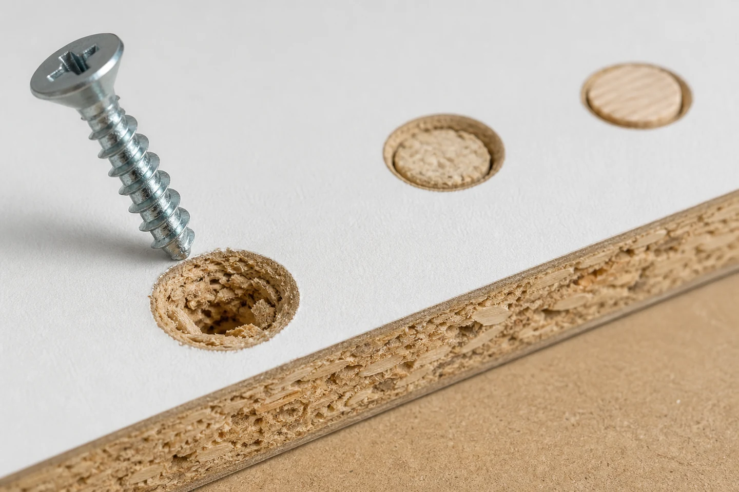
When a chipboard screw spins in hole, the threads are no longer developing a useful tightening response in the existing material. The cause may be an oversized pilot, repeated removal, crushed particles, off-axis driving, a screw that reached full depth before clamping, moisture damage, or a joint load that exceeded what the local board could retain.
The repair should be chosen from the function of the joint and the condition of the component, not from the quickest object that can be pushed into the hole.
Stop turning and classify the symptom
Note whether the screw spins before the parts meet, begins to clamp and then releases, or holds initially but loosens under movement. Check whether the head is bottomed in hardware, whether the screw is the intended length, and whether the connected part can move while the screw turns.
Remove the screw only if the repair procedure allows. Preserve loose board particles and inspect the threads for packed material, wear, damage, or a geometry mismatch. Photograph the face and board edge with the hole location marked.
Score the damaged location before selecting a remedy
| Condition | Evidence to collect | Decision direction |
|---|---|---|
| Hole is clean but visibly oversized | Pilot tool, drill size, process record, screw dimensions | Correct preparation and evaluate an approved repair or new location |
| Board is crushed or crumbling | Edge view, moisture signs, surrounding density, load history | Consider whether local repair can restore the required function |
| Screw was removed several times | Assembly history, thread debris, repeated-service requirement | Review hardware intended for repeated assembly |
| Hole is close to an edge or another fixing | Edge distance, splitting, breakout, adjacent damage | Do not relocate without checking spacing and component design |
| Head bottoms before clamping | Hardware depth, component stack, screw length | Correct the geometry rather than treating it as stripped board alone |
Use the joint consequence to set the repair level
Low-consequence removable trim: a documented local repair may be considered when appearance and positioning are the main functions and the component remains sound.
Moving hardware: hinges, slides, handles, and repeatedly loaded fittings can enlarge weak repairs. The repair needs to address cyclic movement, hardware alignment, and all related fixing positions.
Safety-relevant or heavily loaded connection: do not improvise. Component replacement, engineered hardware, or formal design review may be required. A blog cannot define the acceptable capacity.
Compare four repair paths on scrap first
- Relocate the fixing. This can avoid damaged material, but only when edge distance, hardware position, appearance, and component design permit a new hole.
- Use a purpose-designed insert or repair system. Confirm the board thickness, drilling method, insert dimensions, hardware compatibility, and installation control.
- Change the screw or hardware system. A different approved geometry may suit the application, but a larger screw is not automatically safe near edges or in thin board.
- Replace the component. This may be the most controlled response when material is crushed, wet, split, repeatedly damaged, or responsible for an important load.
Test the intended repair in representative board using the actual hardware and assembly sequence. Inspect clamping, alignment, reverse-side clearance, edge behavior, and whether the repair survives the service movement expected from the joint.
Find the process cause so the next hole survives
If several holes fail, audit the preparation and assembly method. Check pilot diameter and depth, drill runout, screw-to-hole alignment, driver speed and clutch behavior, board support, hardware seating, component stack, and whether operators keep turning after the joint is clamped.
For production, retain a sample showing acceptable seating and define a stop condition. A torque value can be useful only with suitable equipment and a documented method; copying a number between different boards, screws, or drivers can create false confidence.
Document the repair boundary
Record the component, board reference, hole position, screw, hardware, failure stage, selected remedy, test evidence, and who approved the repair. State whether repeated removal is allowed and when the component must be replaced.
The key limitation is that a repair that feels tight during assembly may still lack the durability or capacity required in service. Use the appropriate design and verification process for the product.
Review the Chipboard Screw range and the ProAirNails factory overview. Send the board type, thickness, screw, pilot method, hardware, damaged-hole photographs, and repair test through the inquiry page when a chipboard screw spins in hole.
FAQ
Can I put a larger screw into a stripped chipboard hole?
Only if the component, edge distance, hardware, board thickness, and required performance support that approved change. A larger screw can create splitting, breakout, interference, or another weak installation.
Why does a chipboard screw tighten and then start spinning?
The local particles may crush or strip as clamping load rises, the pilot may be too large, the screw may be misaligned, or the head may reach a geometric stop. Inspect the screw, hole, and complete joint.
When should the chipboard component be replaced?
Replacement should be considered when the board is crumbling, wet, split, repeatedly repaired, close to a critical edge, or responsible for a load that a local repair cannot reliably restore.
A decision record helps prevent the same chipboard screw spins in hole failure from moving to the next assembly station.