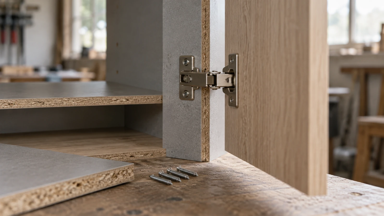

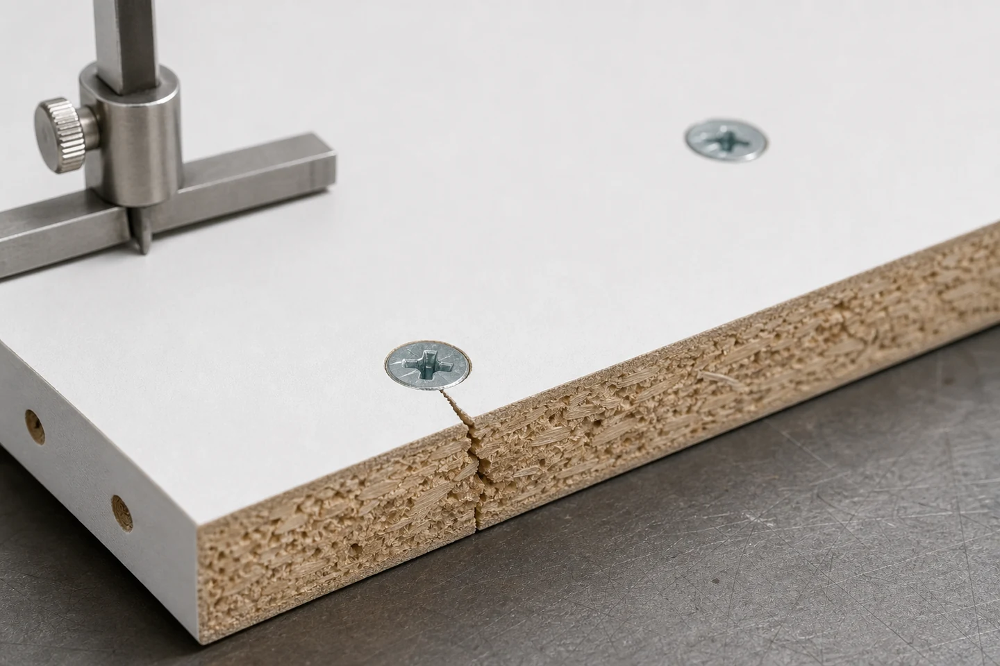
A chipboard screw splits board edge when local expansion and stress exceed what the particle structure can contain at that position. Edge distance matters, but so do pilot preparation, screw diameter and thread, countersink action, board thickness and density, moisture damage, support, alignment, hardware geometry, and how far tightening continues after clamping.
The useful response is an edge-risk card built from representative panels, not a universal distance copied from another screw or board.
Capture the failed edge before opening it
Photograph the face, edge, reverse side, screw head, connected hardware, and the split under side lighting. Mark where the crack began and whether it follows the face layer, particle core, pilot hole, adjacent hole, or hardware edge.
Record whether the split appeared during drilling, screw entry, final tightening, hardware loading, or later service. Preserve loose particles and the removed screw with the location identified.
Build the risk card from seven inputs
- Board manufacturer or reference, thickness, condition, and lot.
- Distance from hole center to each relevant edge.
- Screw diameter, length, head, thread, point, and finish.
- Pilot diameter and depth, including drill condition and runout.
- Driver, bit, alignment, speed, clutch or tightening method.
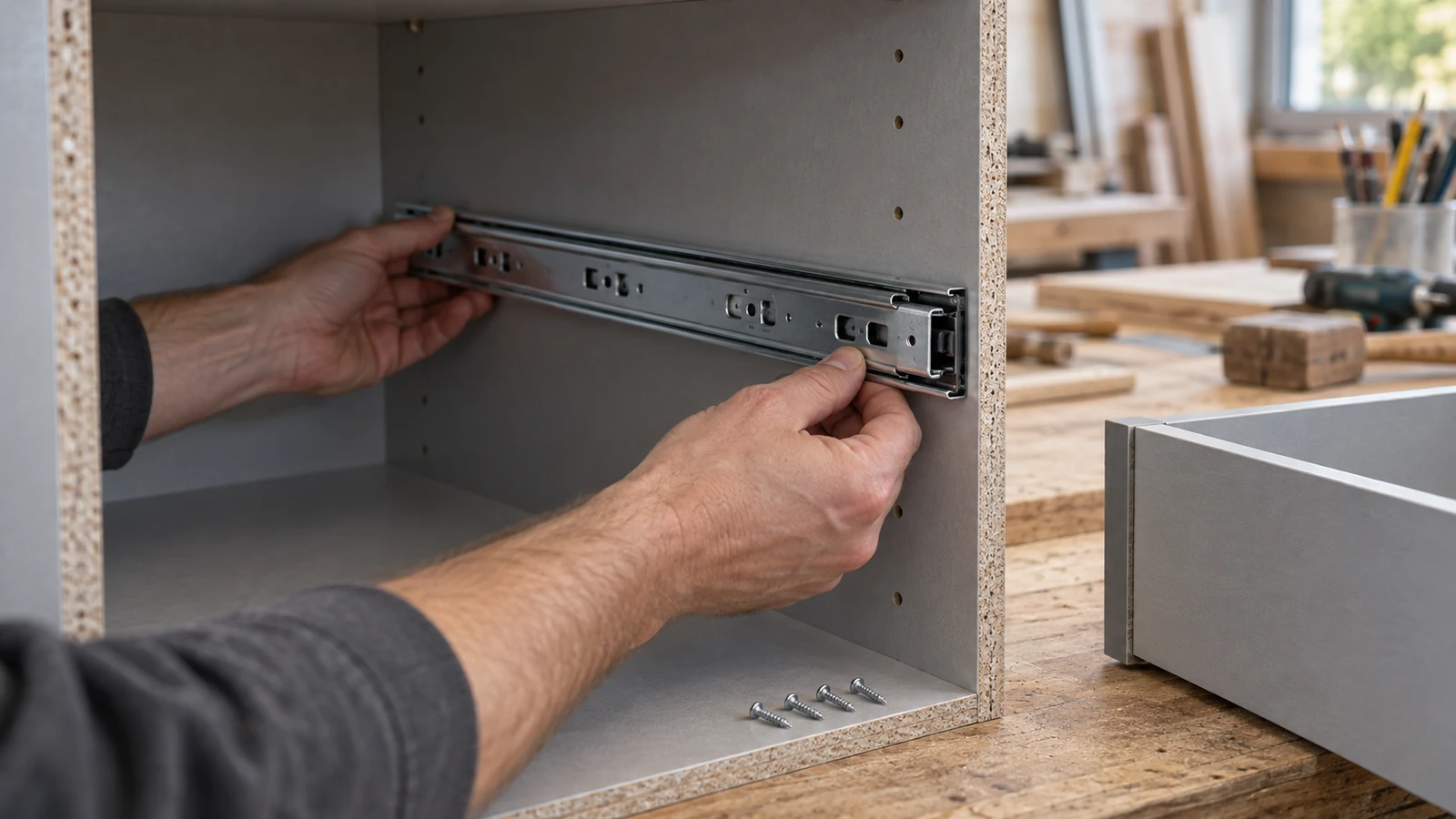
- Hardware hole, countersink, component stack, and clamping sequence.
- Support beneath the board and distance to adjacent fixings.
Missing one of these inputs makes it easy to blame the edge distance for a failure produced by a different combination.
Use a position ladder on scrap from the same board
Lay out several permitted candidate positions from less demanding to more demanding. Keep the screw, pilot, driver, support, hardware simulation, and operator fixed. Install multiple specimens at each position and inspect face bulging, edge cracks, crumbling, seating, spinning, and reverse-side damage.
| Result | Interpretation to test | Next single change |
|---|---|---|
| Split begins during pilot drilling | Drill condition, pilot geometry, edge position, weak board | Inspect drilling method and material |
| Split begins as thread enters | Displacement, alignment, screw geometry, pilot size | Compare one approved preparation change |
| Split begins at final tightening | Head wedging, hardware seating, excessive tightening | Define the clamping stop and geometry |
| Split appears after loading | Joint movement, cyclic load, insufficient local material | Review hardware and component design |
Challenge the best position with real assembly conditions
Add the actual hardware, component stack, access angle, and production support. Test near adjacent holes and on both ends of the permitted board section if the product design includes those positions. A center-board coupon may hide the edge interaction that matters in the finished cabinet.
Inspect the board after a defined waiting period and after the service movement appropriate to the product. Do not create an artificial load without an approved method.
Separate process correction from design correction
A process correction may include a controlled pilot, square alignment, stable support, verified screw, and defined tightening stop. A design correction may require moving the fixing, changing hardware, adding an insert, changing board thickness or construction, or replacing the connection concept.
A larger screw is not automatically a repair. It displaces more material and may worsen edge breakout. Likewise, a larger pilot can reduce splitting but remove material needed for thread engagement. Both outcomes must be evaluated together.
Publish the card with a stop rule
Record the approved board, screw, pilot, position, tool setup, support, hardware, sample photographs, and acceptance criteria. Add a stop rule for crumbling board, visible crack, spinning screw, misaligned hardware, damaged drill, or material change.
The limitation is explicit: the card applies to the tested combination and does not establish structural capacity, furniture safety, durability, or suitability for every board lot. Those outcomes require the appropriate design and performance verification.
Review the Chipboard Screw category and the factory overview. Send the board, screw, pilot, hardware, edge dimensions, failure stage, and sample photographs through the inquiry page when a chipboard screw splits board edge.
FAQ
How close can a chipboard screw be to the board edge?
There is no universal distance independent of board, screw, pilot, hardware, load, and product design. Use the specified requirements and representative tests for the exact combination.
Will a pilot hole stop chipboard edge splitting?
A suitable pilot can reduce local displacement, but an oversized pilot can weaken thread engagement and a poor drilling process can damage the edge. Compare controlled candidates in the real board.
Can a split chipboard edge be repaired?
It depends on the split extent, joint function, edge position, board condition, hardware, and required performance. Important or repeatedly loaded connections may require component replacement or a designed repair.
A tested risk card helps prevent the next chipboard screw splits board edge failure from being repeated across a production batch.