
Evaluate chipboard screws for shelving units by identifying the joint with the smallest damage margin or highest consequence, then validating the full assembly around it. Easy center-panel insertion should not approve a narrow edge, bracket, divider, top, base, or repeatedly assembled joint.
ProAirNails recommends one joint register that connects board, hole, hardware, screw, tool, assembly sequence, design load, and acceptance evidence.
Build the joint register
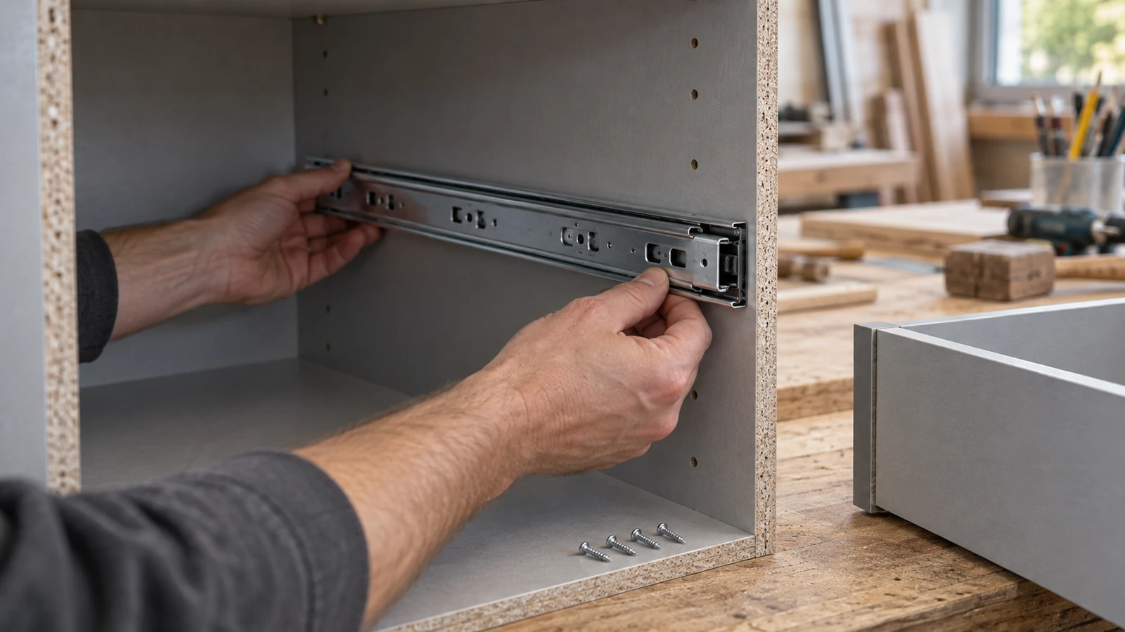
List shelf-to-side, top, base, divider, back, bracket, connector, wall-restraint, and adjustable components as applicable. Record board type, density, thickness, coating, edge distance, hole preparation, mating hardware, access, and screw role.
Rank joints by consequence and margin
| Joint signal | Higher-risk condition | Reason |
|---|---|---|
| Board location | Narrow or cut edge | Less material margin |
| Access | Restricted driver angle | Cam-out or cross-entry |
| Function | Stability-critical connection | Higher consequence |
| Lifecycle | Removal and reassembly | Progressive hole damage |
The product owner and qualified engineering requirements must define loads, stability, restraints, and acceptable joint performance.
Freeze screw, board, hole, and hardware
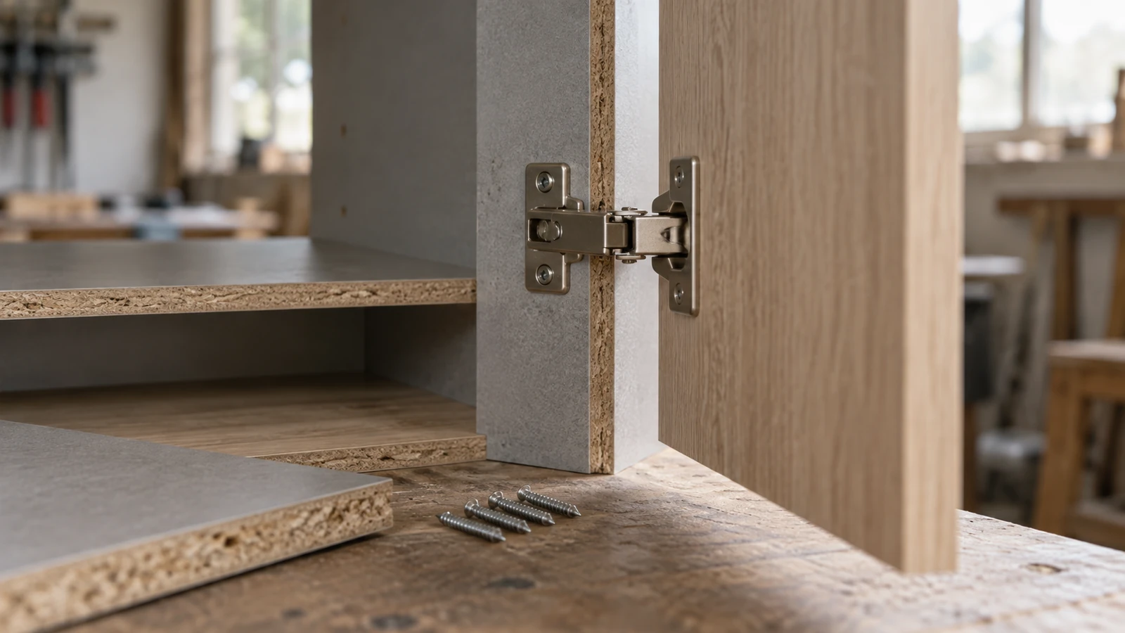
Control screw material, dimensions, head, recess, thread, point, finish, board, coating, production lot, pilot or formed hole, insert or bracket, driver, bit, and target seating. Similar screws are not interchangeable without evidence.
Compare each assembly stage
| Stage | Observe | Release question |
|---|---|---|
| Start | Alignment, wobble, cross-entry | Correct route? |
| Drive | Cam-out, torque behavior, debris | Controlled insertion? |
| Seat | Head position, crush, fit | Joint accepted? |
| Cycle | Removal, hole change, reassembly | Lifecycle met? |
Score board and screw damage
Record edge splits, surface lift, crushing, breakout, hole enlargement, thread debris, spin-out, head or recess damage, coating loss, and component movement. Retain parts and photographs by joint, cycle, screw lot, board lot, tool, and operator.
- Use production holes and hardware.
- Test restricted access realistically.
- Follow the approved assembly sequence.
- Do not hide a stripped joint with an unapproved repair.
- Retain the limiting-joint samples.
Test the complete shelving unit
Build representative sizes with shelves, dividers, backs, doors or brackets, feet, connectors, and restraints as applicable. Apply only product-owner and engineering-defined stability, load, handling, and cycle tests under a safe plan.
Test instructions and part identity
Ask unfamiliar users or representative assemblers to follow controlled instructions. Record wrong-part selection, hesitation, sequence errors, tool angle, excessive tightening, and recovery. Use distinct codes and compartments for similar screws.
Scale samples to the limiting joint
Include board lots, all critical joint types, tools, operators, hardware, access conditions, and claimed cycles. Increase coverage where a failure affects stability or remains hidden after assembly.
The sample plan for chipboard screws for shelving units should define failure counts, hold boundaries, retest, and release authority.
Challenge packing and delivery
Validate hardware bags, compartments, labels, counts, mixed parts, corrosion protection, abrasion, and contact with finished panels after representative handling. Use the ICC Incoterms resource to clarify international responsibilities where relevant.
Use complaint evidence before reorder
Track missing or mixed hardware, assembly errors, stripped joints, board damage, instability, replacements, return reasons, and corrective-action effectiveness. Separate instruction, board, hole, hardware, screw, tool, pack, transport, and use causes.
This keeps chipboard screws for shelving units tied to accepted assemblies rather than unit price.
Release the first unit by joint register
Inspect every registered joint rather than only the finished appearance. Record start, drive, seating, board damage, component alignment, hardware engagement, and required cycle result. Confirm that instructions and part codes lead the assembler to the correct screw at each location. The limiting joint must pass before the whole unit is released.
Scale samples across board and hardware variation
Include ordinary packed screws from several boxes, representative board lots, factory and cut edges, every critical bracket or connector, restricted access, multiple tools, and qualified assemblers. Increase coverage where a failed joint affects stability or remains hidden after assembly.
Keep receiving and assembly releases separate
Receiving can approve identity, dimensions, finish, counts, labels, packs, and visible condition. Assembly must still approve start, drive, seating, board response, hardware fit, limiting-joint evidence, and complete-unit results. Review the ProAirNails fastener range and send controlled screw requirements through the inquiry page.
Use references within scope
The USDA Forest Products Laboratory Wood Handbook provides useful wood-product context, but it does not approve a shelving joint. Qualified product testing and engineering remain necessary.
Define the cycle-test limit
A controlled trial cannot represent every consumer, overload, environment, move, board lot, or future process. Preserve the joint register, approved unit, photographs, specifications, results, and open deviations; reopen affected checks after relevant change. Record who approved the limiting joint, complete unit, instructions, hardware pack, and claimed assembly cycle. Keep replacement-part and complaint evidence linked to the same approved unit and joint register.
Build a ProAirNails screw brief
Review ProAirNails fastener information and related product options. Send joint drawings, board, holes, hardware, tools, cycles, volume, packing, and known failures through the inquiry page. Include current screw samples where available.
Suitable chipboard screws for shelving units must pass the limiting joint and the complete assembly lifecycle.
FAQ
What is the limiting shelving joint?
It is the connection with the smallest margin, most difficult access, greatest damage exposure, or highest failure consequence.
Which joints belong in the register?
Include shelves, sides, top, base, dividers, backs, brackets, connectors, restraints, and adjustable parts as applicable.
What board details should be recorded?
Record type, density, thickness, coating, edge, hole preparation, lot, moisture condition, and relevant variation.
Which screw damage matters?
Inspect head, recess, coating, straightness, thread, point, debris, driver engagement, and deformation after each cycle.
Which board damage matters?
Track splitting, lift, crushing, breakout, hole enlargement, thread debris, spin-out, movement, and alignment loss.
Should instructions be tested?
Yes. Codes, diagrams, sequence, access, tools, counts, and error recovery affect whether the correct screw reaches each joint.
How should similar screws be separated?
Use unique codes, dimensions, compartments, labels, controlled counts, and assembly-step references.
Why test complete units?
Joint interaction, alignment, hardware, stability, handling, loading, and lifecycle cannot be judged from loose board coupons alone.
When should approval be reopened?
Review changes to screw, board, hole, hardware, design, load, tools, instructions, pack, site, process, or criteria.
What supports a quotation?
Send joint drawings, board data, holes, hardware, screw sample, tools, cycles, loads, volume, packing, and failures.