
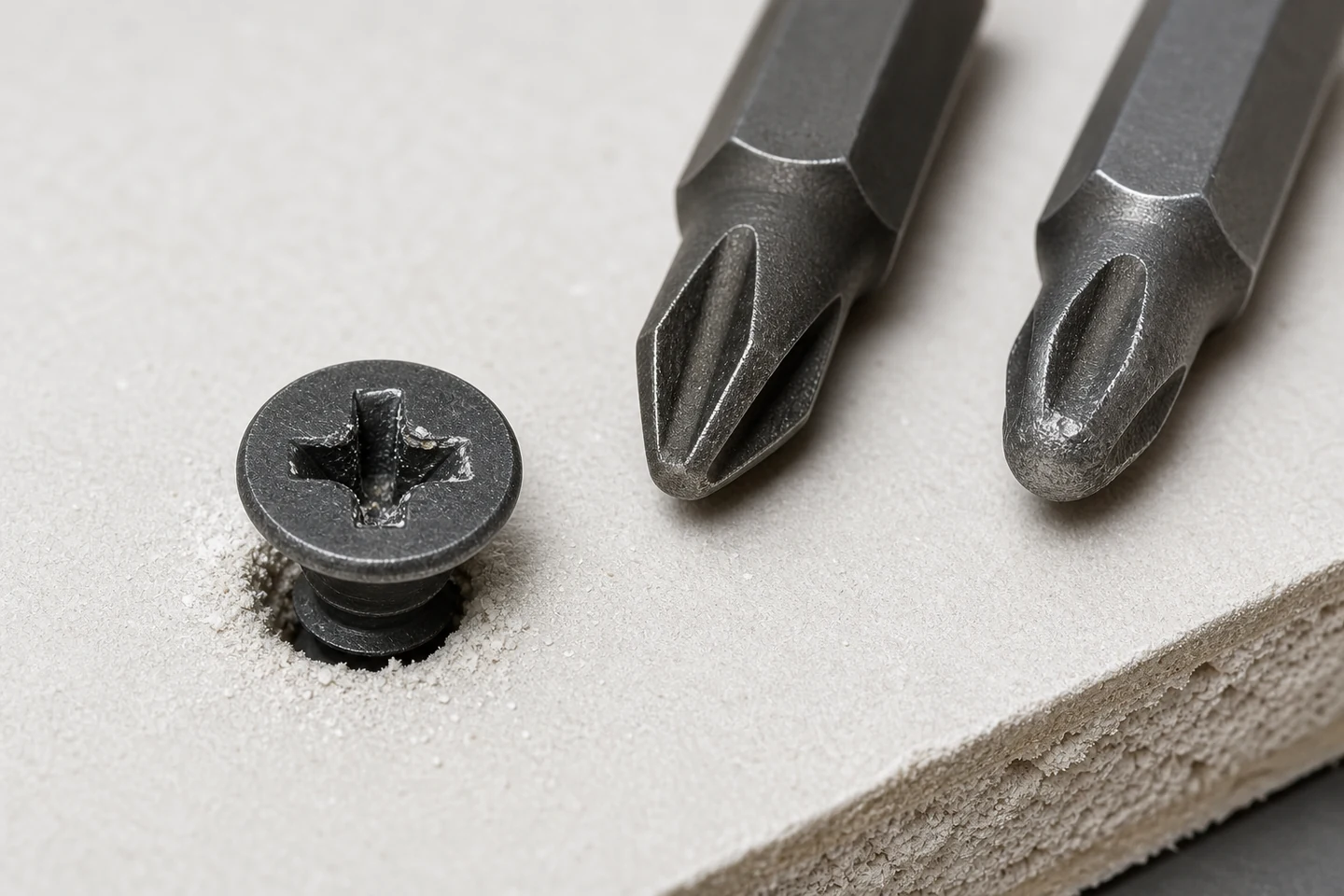
When a drywall screw bit slips, the useful evidence is the contact pattern between the driver and the recess. A rounded bit, shallow engagement, damaged screw recess, off-axis tool, excessive insertion resistance, or an incompatible drive size can all produce a similar jump or cam-out. Increasing force before identifying the interface can erase the evidence and make the next attempt less controlled.
Stop after the first repeatable slip. Keep the screw, bit, board offcut, tool setting, and installation position together so the comparison represents the actual event.
Capture the slip pattern before changing the setup
Photograph the screw head from above and at a low side angle. Record whether the bit climbed out in one direction, rotated without full engagement, or slipped only near final seating. Mark the operator position, tool angle, screw length, board layers, framing material, and whether the screw began straight.
Note the sound and timing. A slip at first contact points toward fit or alignment; a slip after most of the thread has entered may be related to rising resistance, seating control, or a recess that was progressively damaged.
Build a four-piece contact comparison
| Comparison piece | What to inspect | What it helps separate |
|---|---|---|
| Suspect screw | Recess edges, depth, debris, coating damage | Manufacturing, handling, or drive damage |
| Unused screw from the same lot | Fit and recess geometry before installation | Event damage from incoming condition |
| Suspect bit | Rounded wings, chips, polish, contamination | Tooling wear from screw variation |
| Confirmed fresh bit | Full seating and rotational play | Bit condition from system resistance |
Seat each disconnected bit by hand in each screw and compare depth, side play, and visible contact. Do not use a loose-feeling hand check as a performance declaration; it is a screening step that directs the controlled drive test.
Read the recess and bit as one interface
Look for matching polished areas. Contact only at the tips can indicate shallow engagement or a geometry mismatch. Contact concentrated on one side can point toward an angled tool or screw. Metal displaced around the recess usually means the interface has already been overloaded and should not be used for another diagnostic drive.
Confirm the driver type and size specified for the screw. Bits that appear similar may not share the same flank angles or depth. Clean gypsum dust or coating debris from the bit holder and verify that the bit is fully retained.
Change one drive variable at a time
- Use representative board and framing with the original stack thickness.
- Begin with an unused screw and a confirmed fresh compatible bit.
- Hold the tool square and apply stable axial pressure without leaning on the head.
- Use the approved speed, clutch, depth-control, and seating procedure.
- Repeat a small documented sample before changing one variable.
If the fresh combination works, retest the suspect bit only under the permitted procedure. If both bits slip at the same insertion stage, examine resistance, material, screw alignment, thread engagement, and tool control instead of assuming the bit is the only cause.
Separate insertion resistance from final seating
Record whether the screw is entering light-gauge steel, wood framing, multiple board layers, an existing hole, or a hard local feature. Confirm that screw type and length match the application. A recess can fail because the required torque rises beyond what the contact interface can transmit, even when the bit initially fits.
Do not use a higher-impact setting as a universal correction. It may seat some screws while accelerating recess and bit damage, tearing the board face, or hiding an unsuitable screw-material combination.
Set a stop rule for production
Define when operators replace a bit, hold a screw lot, inspect the tool holder, or escalate a repeated location-specific problem. Useful triggers include visible rounding, repeated slips within a defined sample, unstable bit retention, damaged unused recesses, or slips that follow one material stack.
The limitation is important: this comparison does not prove screw conformity, tool safety, installation capacity, or finished wall performance. Those conclusions require the applicable product criteria, tool inspection, project requirements, and qualified authority.
Review the Drywall Screw category and the broader screw range. Send screw reference, bit type, board and framing stack, tool settings, contact photographs, and test sequence through the inquiry page when investigating why a drywall screw bit slips.
FAQ
Does a slipping drywall screw always mean the bit is worn?
No. Bit wear is common, but an incompatible size, shallow engagement, damaged recess, angled drive, high insertion resistance, debris, or unstable bit retention can create the same symptom.
Can more pressure stop the bit from camming out?
Stable axial contact helps, but excessive force does not correct incompatible geometry or abnormal resistance. It can damage the recess, board surface, tool control, or operator position.
Should a screw be reused after the driver has slipped?
A visibly damaged recess should not be relied on for another diagnostic drive. Follow the project and installation requirements for removal and replacement, and preserve the screw if it is needed as evidence.
A matched contact set turns drywall screw bit slips from a vague tool complaint into a traceable interface investigation.