
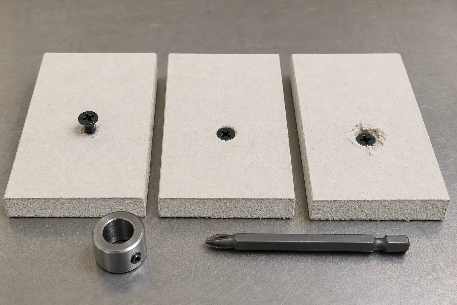
A drywall screw head seating depth window is the controlled range between a head left too proud for finishing and a head driven so far that the gypsum board paper face tears or loses effective support. It is a process window, not one universal depth number, because board density, framing, screw geometry, tool control, angle, and operator technique all change the resulting seat.
ProAirNails recommends defining physical states on representative panels, then finding tool settings that repeatedly land inside the accepted state under declared boundary conditions.
Name the three seating states before measuring them
A proud head stands above or insufficiently below the paper face and can interfere with finishing. An accepted seat forms the specified dimple while preserving the face paper around the head. An overdriven seat tears, cuts, or severely crushes the paper. Borderline samples should be retained so inspectors share the same visual language.
Build a depth ladder, not a single target
Prepare representative board and framing. Starting from a conservative setting, advance the control in documented increments and drive a fixed number at each level. Include normal, slightly angled, edge-near, joint-near, and harder or softer support conditions only when they represent the installation. Do not mix them without location codes.
Record inputs beside every outcome
| Input group | Record | Why it matters |
|---|---|---|
| Screw | Type, length, head, thread, coating, lot | Engagement and head-to-paper interaction |
| Board | Type, thickness, batch, condition | Face and core response |
| Framing | Material, thickness, location, support | Driving resistance |
| Tool | Model, nosepiece, setting, speed | Depth control and repeatability |
| Operator | Angle, pressure, sequence | Applied boundary condition |
Judge paper continuity before depth alone
Use side light and close inspection to identify rings, cuts, lifted paper, torn fibers, and crushed core. A depth reading without paper condition can misclassify an overdriven head as acceptable. Conversely, a visually intact seat should still be checked against the finishing requirement and attachment specification.
- Mark each drive location and setting.
- Keep accepted boundary samples.
- Photograph normal and raking-light views.
- Cut sections only after surface inspection.
- Record every tool adjustment and intervention.
Locate the center of the stable region
Choose a setting that produces margin on both sides of the accepted zone, rather than one that barely avoids a proud head in the easiest panel. Challenge that center setting across representative board joints, framing positions, operators, and tool wear states. The usable drywall screw head seating depth window should remain stable across those declared conditions.
React to each pattern differently
| Pattern | Likely investigation | Controlled response |
|---|---|---|
| Mostly proud | Setting, engagement, tool approach | Advance within the ladder |
| Mostly torn paper | Excess depth, pressure, soft board | Back off and verify center |
| Proud and torn in one setting | Variation in support, angle, or tool | Reduce process variation first |
| Failures near edges only | Location and support boundary | Define edge method separately |
| Drift over a long run | Nosepiece wear or setting movement | Add interval checks |
Separate screw specification from installation variation
Compare retained screw samples and verify identity, but do not assume every seating defect originates in the fastener. Repeat with controlled tool, board, framing, and operator conditions. If the outcome follows a screw lot while other inputs remain fixed, preserve that evidence; if it follows the tool or location, correct the corresponding process.
Place the product standard in context
The official ASTM C1002-22 page covers steel self-piercing tapping screws used for gypsum panel products. It does not define the finish-ready dimple, tool setting, board condition, or acceptance panel for every project.
Use torque data as supporting evidence
The ISO 16047:2005 page addresses torque/clamp-force testing for threaded fasteners under stated conditions. It does not directly reproduce gypsum paper seating, and torque should not be converted into a universal depth setting without representative board trials.
Control production with boundary samples
Place photographs or retained examples of the shallow acceptable edge, preferred center, deep acceptable edge, and failure states at the inspection point. Check at startup, after adjustment, after interruptions, and at declared intervals. Record the affected production span when a result leaves the window.
Bring the complete panel map to ProAirNails
Provide screw specification and lot, board and framing, tool and nosepiece, settings, operator method, depth-ladder map, paper condition, sections, defect locations, and acceptance states. ProAirNails can discuss drywall screws, the broader screw range, related products, and samples through the inquiry page.
Keep the window attached to its conditions
A drywall screw head seating depth window cannot guarantee structural capacity, finishing quality, or performance outside the tested board, framing, screw, tool, operator, and environment. It does not replace project specifications, code requirements, or equipment instructions. ProAirNails can support identified screw evidence; the installer controls the field process.
Retain the ladder and center-setting results. Reconfirm the drywall screw head seating depth window after changes to screw, board, framing, tool, nosepiece, operator method, or acceptance criteria.
FAQ
Is a deeper screw always better seated?
No. Excess depth can tear the paper face and reduce the support around the screw head.
What is a proud drywall screw?
It is a screw whose head remains above or insufficiently below the required finished surface.
Why use a depth ladder?
It reveals the transition from proud to accepted to overdriven states and shows available process margin.
Should depth be judged without inspecting paper?
No. Paper continuity is essential because a low head can still be overdriven.
Why retain borderline samples?
They help operators and inspectors apply the same physical acceptance rule.
Can one tool setting work for every board?
No. Board density, framing, tool condition, angle, and operator pressure can change seating.
What causes both proud and torn results at one setting?
Large variation in support, angle, tool response, or board condition can collapse the stable region.
When should production checks occur?
Check at startup, after adjustments or interruptions, and at defined intervals during the run.
Does torque alone define seating depth?
No. Torque data and representative board-surface evidence answer different parts of the decision.
What information helps investigate a complaint?
Send screw identity, materials, tool settings, panel map, paper evidence, defect locations, and retained samples.