
Drywall screw paper tear prevention depends on stopping the screw at the approved dimple while the paper face remains intact around the head. The paper is part of the board surface system. A screw that cuts through it may look deeply seated, but depth alone does not prove that the attachment remains acceptable.
ProAirNails recommends controlling the complete drive chain: correct screw and framing match, supported board, aligned tool, stable speed, suitable depth-control device, trained operator, and a sample panel that shows proud, accepted, and torn-paper states.
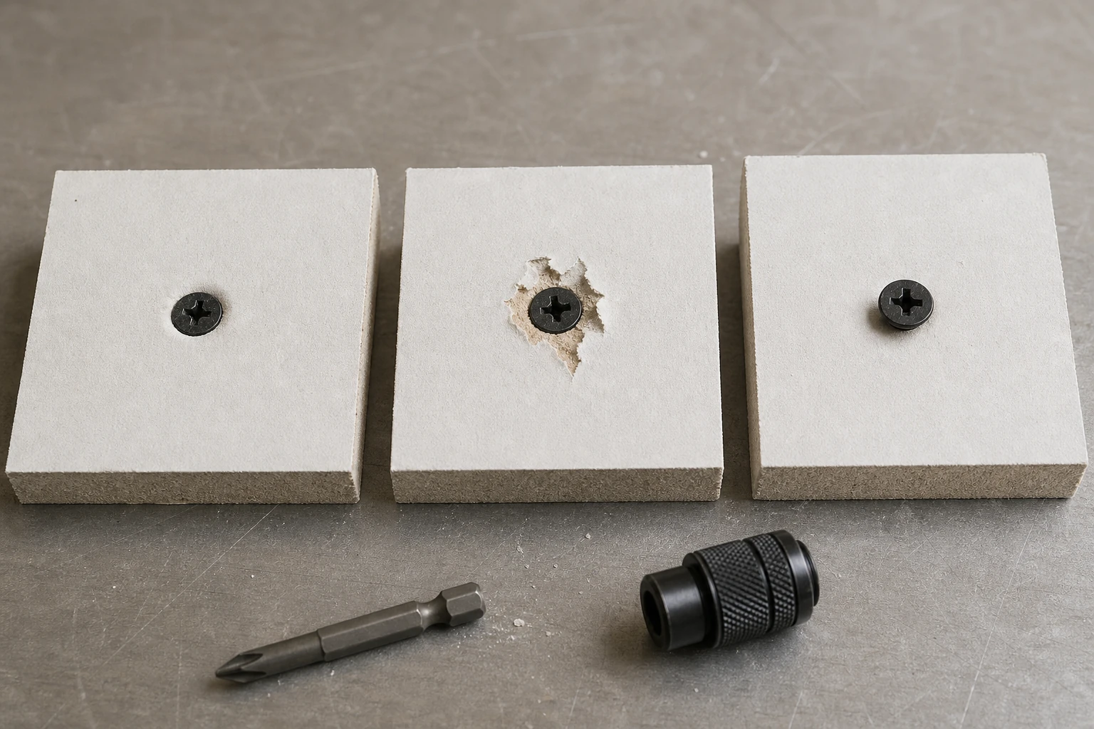
Read the three seating states
| State | Visible evidence | Process response |
|---|---|---|
| Proud | Head above target surface | Check engagement, depth, support, and driver |
| Accepted dimple | Controlled recess with intact paper | Retain as the setup reference |
| Torn paper | Broken or lifted fibers around head | Stop, contain, and correct the drive route |
| Deep breakout | Head enters gypsum core | Apply approved repair or replacement rule |
| Angled seat | One head edge deeper than the other | Review alignment and board contact |
Protect the paper by supporting the board
Seat the panel against the framing member before driving. A gap can close suddenly and pull the head through the face. Record board thickness, type, condition, framing material and thickness, alignment, edge distance, and whether the screw actually enters the intended member.
Match screw tool and framing
Confirm length, diameter, thread, point, head, recess, finish, driver bit, tool, and substrate. A worn bit or mismatched recess can wobble and produce an angled seat. A screw selected for wood framing may not behave like one selected for a specified steel thickness. Follow applicable board, tool, and project requirements.
Set depth with a real sample panel
Use representative board and framing rather than adjusting on scrap wood. Begin conservatively, drive several fasteners, inspect paper continuity and head position, then adjust one setting at a time. Retain the accepted panel near the setup area so operators have a physical reference.
- Verify bit condition before setup.
- Hold the tool square to the panel.
- Support the board against framing.
- Inspect after speed or operator changes.
- Separate repair from normal acceptance.
Control the variables that move during a shift
Track driver-bit wear, nosepiece contamination, depth-stop movement, tool speed, battery or power state, board gaps, framing variation, operator fatigue, and repeated driving near edges. A setup that passed at shift start can drift. Use periodic challenge checks with the same accepted reference state.
Distinguish a dimple from a rupture
Inspect under consistent light and at a useful angle. A controlled dimple depresses the face around the head without severing it. Torn fibers, radial cuts, missing paper, exposed gypsum, or a head below the paper layer indicate another state. Do not hide the evidence with compound before disposition.
Build prevention into the response
| Repeated pattern | Likely investigation | Control |
|---|---|---|
| All heads too deep | Depth setting or stop | Reset on representative panel |
| One operator sees tears | Alignment, speed, or pressure | Observe method and retrain to reference |
| Tears near unsupported edges | Board contact and geometry | Correct support and fastening layout |
| Angled tears with recess marks | Bit wear or mismatch | Verify bit and screw engagement |
| Random depth changes | Tool, framing, or board variability | Separate conditions and expand checks |
Define repair before production
Specify who can judge a torn face, whether an adjacent screw is required, minimum spacing, how the failed screw is treated, and what documentation is retained. Do not improvise by driving another screw beside every concern without checking project requirements and edge distances.
Use the product standard accurately
The official ASTM C1002-22 page covers steel self-piercing tapping screws for applying gypsum panel products or metal plaster bases to specified wood or steel members. It does not choose the tool depth, board support, installer technique, or project repair rule.
Sample by process state
The ISO 2859-1:2026 page describes AQL-indexed lot-by-lot attribute sampling. Installation monitoring also needs samples across tools, operators, framing, time, and setup changes. A carton-level pass cannot prove every installed screw preserves the paper face.
Send an installation-ready inquiry
Provide screw specification, framing, board, tool and bit, depth device, accepted sample, seating images, line speed, defects, repair rule, and acceptance. ProAirNails can discuss drywall screws, the broader screw range, available products, and samples through the inquiry page.
Keep prevention connected to the project
Drywall screw paper tear prevention cannot guarantee joint performance, finishing quality, fire resistance, or code compliance by itself. Follow the board system, framing, tool, design, and applicable project instructions. ProAirNails can support identified screw evidence; the installer and designer control the assembly.
Repeat the setup after changing board, framing, screw, bit, tool, power source, operator, speed, or depth device. Retain accepted and rejected reference coupons. Use drywall screw paper tear prevention as a visible process control, not a repair step after compound hides the surface.
Track torn-paper events by tool, operator, time, board, framing, and location. A pattern is more actionable than a total count without context.
Use drywall screw paper tear prevention to stop at the point where the head is seated and the face still performs its intended role.
FAQ
Is a deeper screw always better?
No. The target is controlled seating with the paper face intact, not maximum depth.
What is an accepted drywall screw dimple?
It is the project-approved recess around a seated head without cut or missing paper.
Why does a board gap matter?
The board can move suddenly toward framing and pull the screw through the paper.
Can a worn bit cause tearing?
Yes. Wear or mismatch can cause wobble, angled seating, slips, and unstable control.
Should torn paper be covered immediately?
No. Preserve and disposition the evidence before finishing compound hides it.
How often should setup be checked?
Check at startup and after relevant tool, bit, board, framing, operator, speed, or power changes.
Does a product standard set tool depth?
No. Tool setup and assembly acceptance remain application-specific.
Can an extra screw be added anywhere?
No. Follow the approved repair, spacing, edge-distance, and assembly requirements.
What should an accepted sample show?
Show head position, intact paper, board support, screw identity, framing, and approved viewing rule.
What data helps investigate recurring tears?
Record tool, bit, operator, time, board, framing, location, setting, image, and response.