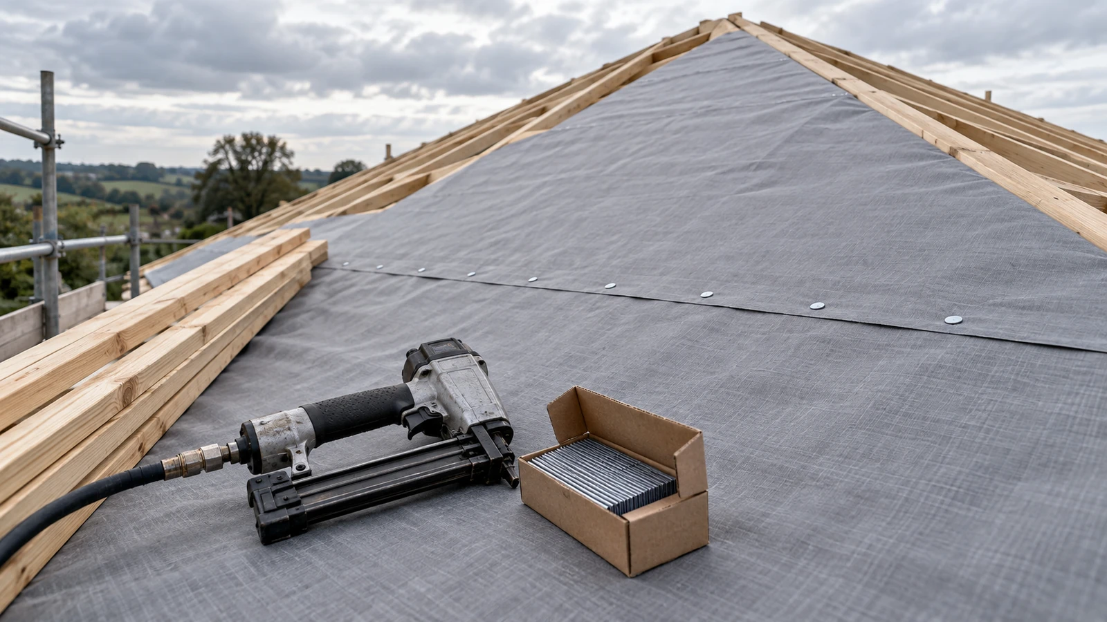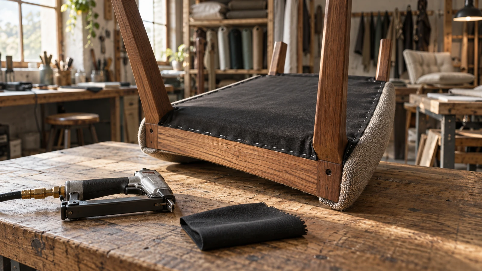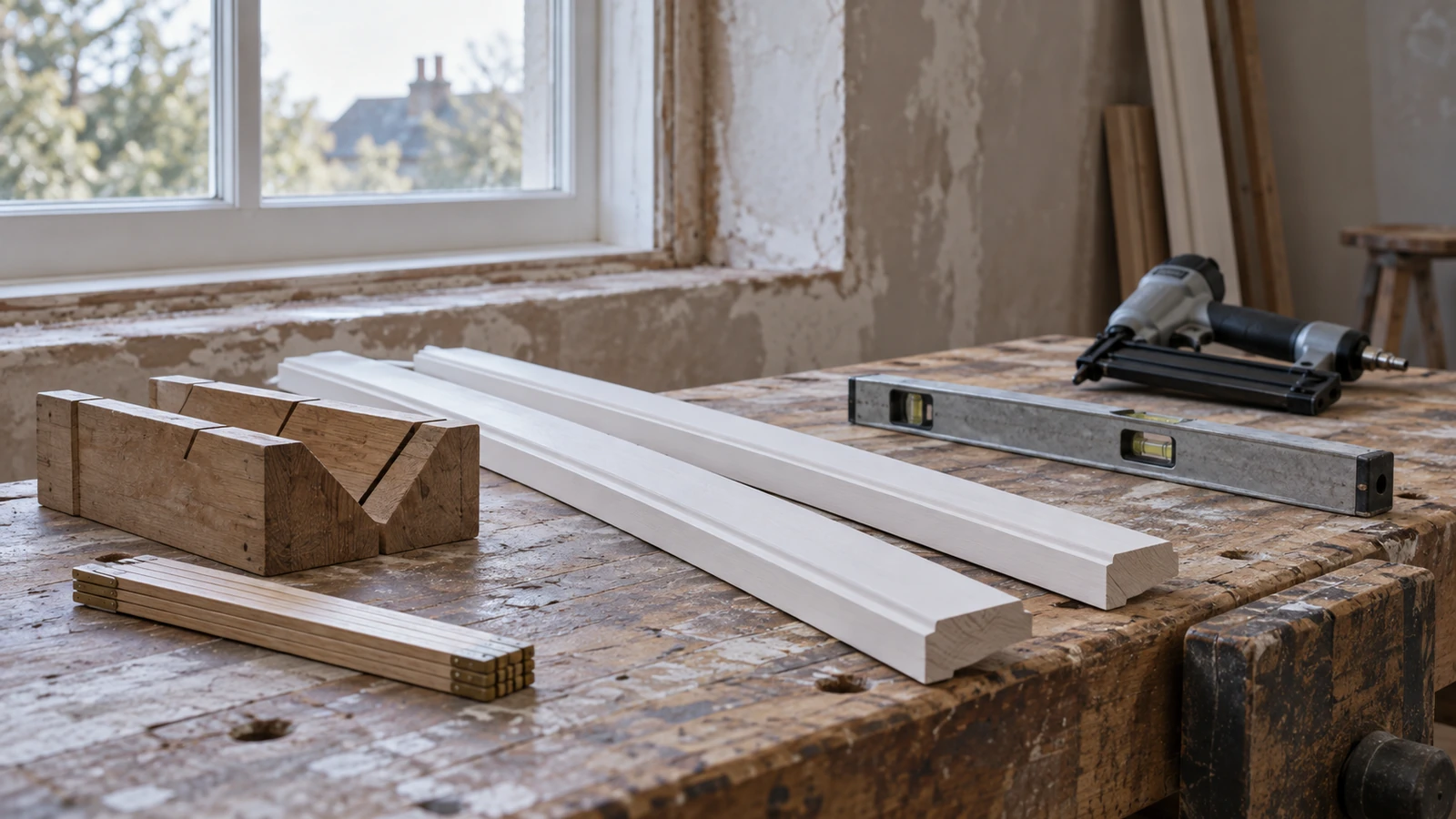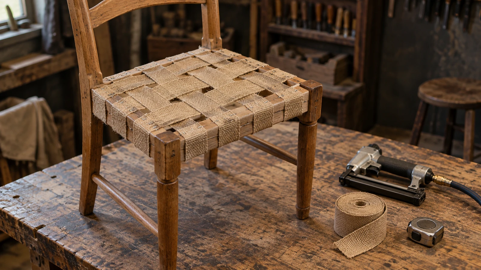

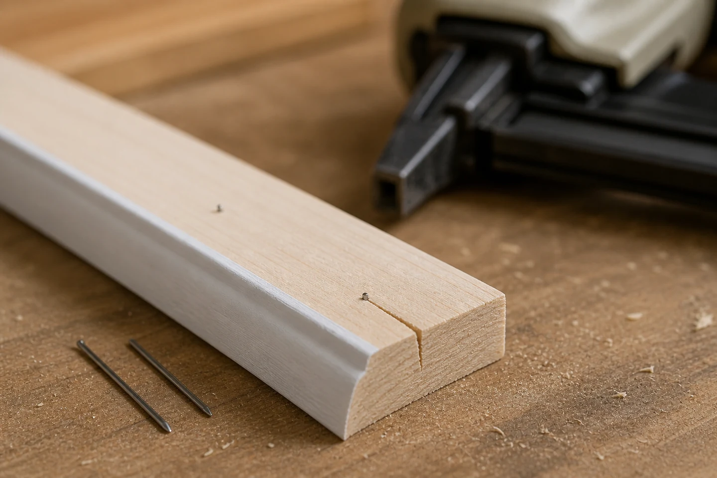
Pin nails splitting thin trim usually reflects a narrow margin for error rather than one isolated variable. A pin near the end can meet short grain, follow grain runout, enter at an angle, cross a hard growth feature, or force apart material that is unsupported or already stressed by fit-up. The crack may be small at installation and open later during finishing or service.
Keep the failed piece if possible. Mark the visible face, tool direction, pin position, grain direction, and installation order before removing the fastener or trimming away the split.
Trace the crack back to its first visible point
Use raking light and magnification to determine whether the split starts at the pin entry, the trim end, a miter, a profile corner, or a pre-existing defect. Photograph the full component and a close view with a scale. Measure the pin center to the end, edge, groove, rabbet, and thinnest part of the profile.
A crack that begins at the entry suggests a different path from one that begins at the end and merely passes the pin. Preserve that distinction in the record.
Draw the available entry corridor
Sketch the trim cross-section and mark the material that can safely receive the intended pin path. Decorative profiles often have less effective thickness than their outside dimensions imply. The tool nose may sit on a curved or painted face while the pin enters a thin web.
- Show the permitted fastening face and hidden voids or grooves.
- Mark grain direction and visible runout near the end.
- Record the joint below the trim, including gaps and hard substrates.
- Identify the intended pin angle and the possible deflection envelope.
Create an edge-distance ladder on real offcuts
Prepare offcuts from the current trim lot and mark several distances from the end and edge. Keep pin series, length, tool, pressure, depth, support, and operator fixed. Install a small sample at each position, then inspect the face, edge, end, and reverse side.
Do not treat the smallest distance that survives one shot as the production limit. Repeat across grain patterns, including straight grain and visible runout, and retain accepted and failed samples. The purpose is to find a stable working zone with margin.
Rotate grain, tool, and sequence separately
| Test change | Keep fixed | Evidence to watch |
|---|---|---|
| Rotate trim grain orientation | Tool and pin direction | Whether the split follows the wood |
| Change permitted entry direction | Same marked material zone | Whether the crack follows the tool path |
| Change fastening order | Joint fit and pin setup | Whether accumulated stress opens the end |
| Add full backing support | Same trim and pin position | Whether bounce or gap contributes |
Changing all four at once may stop the split without showing which condition controlled it. Document one comparison at a time.
Check the joint before blaming the pin diameter
Dry-fit the trim and look for forced bends, tight miters, adhesive beads, uneven backing, clamps that preload the end, or a pin path entering harder material below. Confirm pin length and tool compatibility. A longer pin can increase opportunity for deflection, while a shorter pin may not provide the required engagement.
Material moisture and brittle coatings also matter. Let trim condition stabilize as required, and test primed or finished pieces when coatings are part of the real process.
Release a trim-specific fastening boundary
Record approved zones, pin reference, tool, support, angle, sequence, and visible acceptance criteria. Define where pins are prohibited and when an alternate joint method is required. Include a normal-view photograph as well as the close inspection view.
The limitation is scope: an offcut test does not establish structural capacity, long-term joint durability, suitability for every wood lot, or compliance with a design specification. Those decisions require the responsible project method.
Review the Pin Nails category and the wider pneumatic fastener range. Send the pin series, tool model, trim profile, edge distances, grain photographs, and joint stack through the inquiry page when examining pin nails splitting thin trim.
FAQ
Will a shorter pin always prevent thin trim from splitting?
No. Length can affect deflection and engagement, but edge distance, grain, entry angle, support, joint stress, profile thickness, and material condition still control the result.
Can the split be hidden with filler?
Filler may disguise a cosmetic line but does not restore an unknown internal path or joint condition. Determine whether the component and fastening result meet the required acceptance standard.
Should pin nails be angled near the end of molding?
Only when the application and approved process permit it. Angling changes the internal path and can move the pin toward an edge or thin profile zone, so it should be verified on representative offcuts.
A documented entry corridor makes pin nails splitting thin trim easier to prevent before finished components reach final assembly.