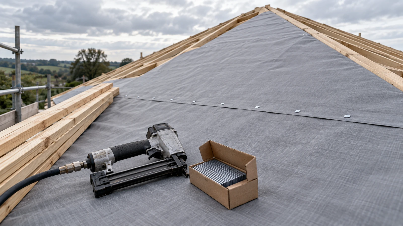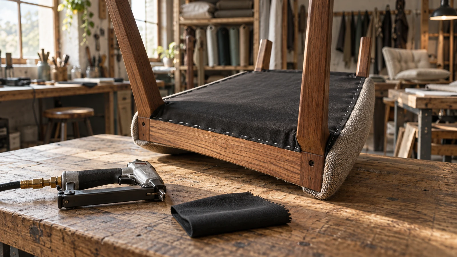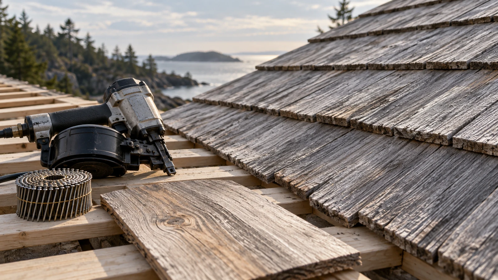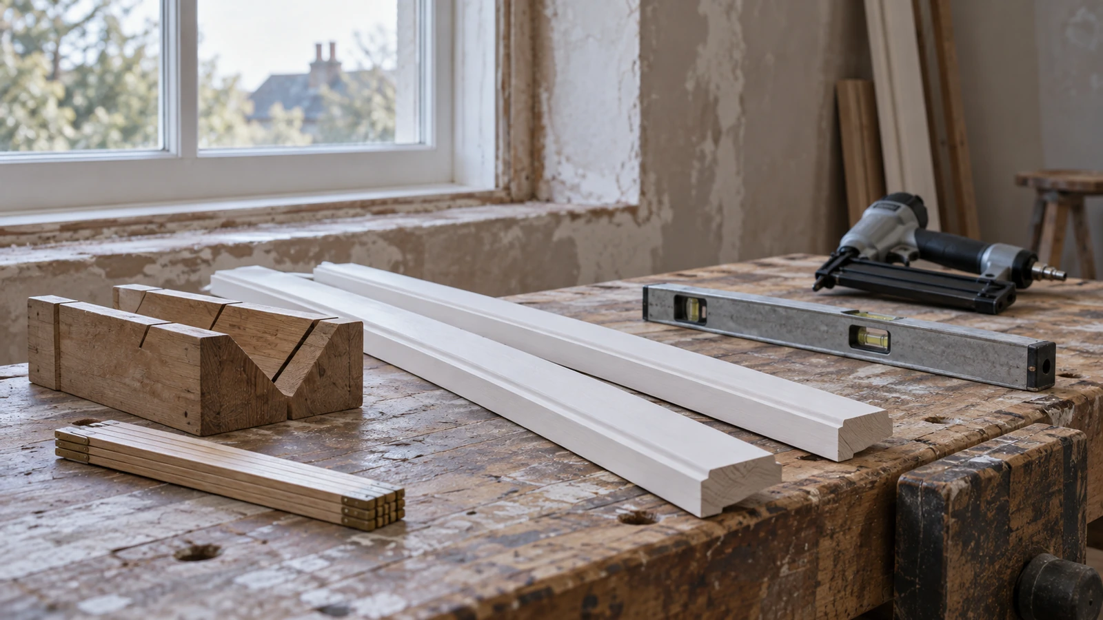

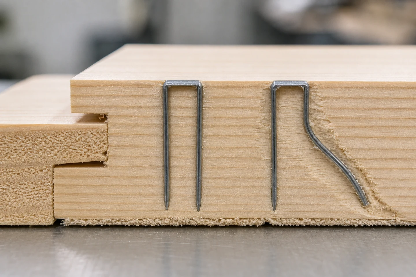
Staple legs bending in wood can remain hidden until a leg exits the edge, a joint loosens, or a rejected sample is cut open. The crown may look evenly seated while one leg follows grain, strikes a dense feature, buckles near entry, or spreads away from the intended path.
Surface appearance therefore cannot be the only acceptance signal. A controlled cross-section provides direct evidence of the path inside the receiving material.
Select specimens that represent different outcomes
Keep one apparently successful joint, one joint with visible side breakout, and one from a location where the crown or driving sound appeared unusual. Mark tool direction, crown orientation, grain direction, entry face, nearest edge, and workpiece support before cutting.
Do not pull the staple first. Extraction can straighten a bent leg or tear a new path that hides the original deflection.
Open the section without moving the evidence
Use an approved workshop cutting and preparation method away from the fastener. Approach gradually until the leg path is visible, then clean loose dust without scraping the metal or surrounding fibers. Photograph the full section and close views with a scale.
Record where the curve begins: immediately below the crown, midway through the wood, near a glue line, beside a knot, or close to the reverse surface. The starting point directs the next comparison.
Match the internal path to the likely variable
| Cross-section pattern | Variable to check | Controlled comparison |
|---|---|---|
| Both legs lean in the same direction | Tool angle, nose contact, workpiece movement | Square and fully support the sample |
| One leg follows visible grain | Grain runout, local density, entry orientation | Rotate clear-grain blocks while keeping setup fixed |
| Leg buckles close to entry | Wire, point, hard feature, driver or feed condition | Inspect tool and compare a confirmed strip |
| Legs spread near the reverse face | Material thickness, point behavior, boundary condition | Compare the actual stack and permitted length |
Rotate the material and the crown separately
Prepare clear offcuts from the current material and mark grain direction. In the first series, rotate the wood while keeping crown orientation relative to the tool unchanged. In the second, keep the wood fixed and rotate the tool or crown orientation where the application permits.
If the leg path follows the wood, material structure may dominate. If it stays aligned with the tool, investigate entry angle, driver, nose, staple condition, and support. If the result is random, widen the sample across material and strip positions.
Check the full stack, not only the receiving block
A flexible top layer, gap between components, unsupported edge, adhesive bead, or uneven clamping can change the entry condition. Measure the actual stack and confirm that the staple series, crown, wire, point, leg length, tool, and magazine are compatible.
Changing to a shorter leg or higher drive setting is not a universal solution. A shorter leg may not provide the required engagement, while greater energy may increase breakout or tool wear without correcting deflection.
Turn the section into an inspection reference
Retain accepted and rejected sections with the material, staple, tool, setup, orientation, and test date. Add face, edge, reverse, and cut-section photographs. Define when production requires another section check, such as after a wood species, moisture condition, staple, tool, or joint change.
The limitation is that a visible straight path does not establish joint strength, durability, code compliance, or suitability for every material lot. Performance needs the appropriate design and verification method.
Review the Air Staple Pin category and the wider pneumatic fastener range. Send the staple series, tool model, material, joint stack, orientations, and cross-section photographs through the inquiry page when examining staple legs bending in wood.
FAQ
Why does only one staple leg bend?
One leg may meet different grain, a dense feature, a glue line, damaged point geometry, or an entry condition that loads the legs unevenly. A cross-section and rotated sample can help separate these factors.
Will a heavier staple wire prevent leg deflection?
Wire section changes behavior but must remain compatible with the tool and joint. Material, point, length, support, grain, and entry angle still matter, so compare approved candidates in the real stack.
Can a bent staple still hold the joint?
Surface appearance cannot answer that. Deflection changes the internal path and may affect engagement or cause hidden damage. Evaluate the joint with the required performance method.
Opening a representative section makes staple legs bending in wood visible, traceable, and easier to compare across changes.